Circuit board cutting device capable of adjusting cutting position conveniently

A cutting device and circuit board technology, which is applied in metal processing and other directions, can solve the problems of reducing the cutting accuracy of circuit boards and the inability to adjust the cutting position of circuit boards, and achieve the effect of improving accuracy

Active Publication Date: 2020-04-10
南京市旗心电子科技有限公司
View PDF10 Cites 4 Cited by
  • Summary
  • Abstract
  • Description
  • Claims
  • Application Information

AI Technical Summary

Problems solved by technology

[0004] It is found that the existing electronic product production is convenient for adjusting the cutting position. When adjusting the position of the circuit board, it can only change the position of the circuit board in a large range, and cannot accurately adjust the cutting position of the circuit board. , which reduces the cutting accuracy when cutting circuit boards

Method used


Image

  • Circuit board cutting device capable of adjusting cutting position conveniently
  • Circuit board cutting device capable of adjusting cutting position conveniently
  • Circuit board cutting device capable of adjusting cutting position conveniently

Examples


Embodiment 1

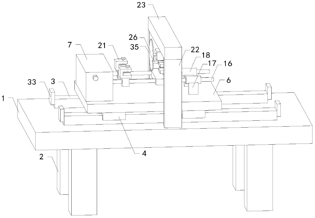
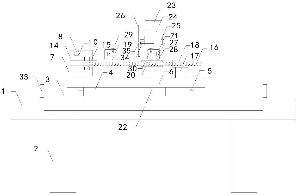
[0027] see Figure 1-2 with Figure 4-5, a circuit board cutting device for adjusting the cutting position of the present invention, comprising a workbench 1, four sets of support legs 2, two sets of adjustment guide rails 3, four sets of adjustment sliders 4, four sets of first fixing buckles 5, adjustment Plate 6, adjustment box 7, adjustment worm 8, transmission rod 9, adjustment worm wheel 10, transmission gear 11, two groups of rotating rods 12, two groups of rotating gears 13, two groups of adjusting screw pipes 14, two groups of adjusting gears 15, two groups of Adjusting threaded rods 16, two sets of support rods 17, two sets of support tubes 18, two sets of cutting tubes 19, support plates 20, three sets of fixing frames 21, two sets of columns 22, horizontal plates 23, cutting sliders 24, cutting motors 25 and cutting saw blade 26, the four sets of supporting legs 2 are respectively fixed on the left front side, right front side, left rear side and right rear side o...

Embodiment 2

[0029] see figure 1 with Figure 3-5 , a circuit board cutting device for adjusting the cutting position of the present invention, comprising a workbench 1, four sets of support legs 2, two sets of adjustment guide rails 3, four sets of adjustment sliders 4, four sets of first fixing buckles 5, adjustment Plate 6, adjustment box 7, adjustment worm 8, transmission rod 9, adjustment worm wheel 10, transmission gear 11, two groups of rotating rods 12, two groups of rotating gears 13, two groups of adjusting screw pipes 14, two groups of adjusting gears 15, two groups of Adjusting threaded rods 16, two sets of support rods 17, two sets of support tubes 18, two sets of cutting tubes 19, support plates 20, three sets of fixing frames 21, two sets of columns 22, horizontal plates 23, cutting sliders 24, cutting motors 25 and cutting saw blade 26, the four sets of supporting legs 2 are respectively fixed on the left front side, right front side, left rear side and right rear side of ...


PUM


Abstract

The invention relates to the technical field of electronic product production, in particular to a circuit board cutting device capable of adjusting a cutting position conveniently. The device can accurately adjust the cutting position of a circuit board and improve the cutting precision of the circuit board, and comprises a workbench, four groups of supporting legs, two groups of adjusting guide rails, four groups of adjusting sliding blocks, four groups of first fixing buckles, an adjusting plate, an adjusting box, an adjusting worm, a transmission rod, an adjusting worm wheel, a transmissiongear, two groups of rotating rods, two groups of rotating gears, two groups of adjusting threaded pipes, two groups of adjusting gears, two groups of adjusting threaded rods, two groups of supportingrods, two groups of supporting pipes, two groups of cutting pipes, a supporting plate, three groups of fixing frames, two groups of vertical columns, a transverse plate, a cutting sliding block, a cutting motor and a cutting saw blade. The four groups of supporting legs are fixed on the left front side, the right front side, the left rear side and the right rear side of the bottom of the workbench correspondingly, the front side and the rear side of the top of the workbench are provided with two groups of adjusting grooves, and the two groups of adjusting guide rails are arranged inside the two groups of adjusting grooves correspondingly.

Description

technical field [0001] The invention relates to the technical field of electronic product production, in particular to a circuit board cutting device which is convenient for adjusting the cutting position. Background technique [0002] As we all know, a circuit board cutting device for electronic product production is a device used for cutting circuit boards during the production of electronic products, and has been widely used in the field of electronic product production. [0003] The Chinese Patent No. CN108943098A discloses a kind of invention patent for the production of electronic products to facilitate the adjustment of the cutting position, which is roughly described as: including a base, the top outer wall of the base is connected with a collection box by bolts, and the top of the outer wall of the collection box is welded There are two symmetrically arranged connecting frames, and the outer walls of the opposite sides of the two connecting frames are welded with th...

Claims


Application Information

Patent Timeline
Patent Type & Authority Applications(China)
IPC IPC(8): B26D1/15B26D7/01B26D7/00
CPCB26D1/15B26D7/00B26D7/01B26D2007/0012
Inventor 陈志勇龙恩朱和梁
Owner 南京市旗心电子科技有限公司
Why Eureka
Try Eureka