
Muscle retractor for general surgery operation

A technology for surgery and general surgery, applied in the field of surgical muscle retraction equipment, can solve the problems of inconvenient operation and adjustment, complex structure of muscle traction devices, etc., and achieve the effect of simple structure, convenient operation, and improved stability

Active Publication Date: 2020-04-10
周龙安
View PDF12 Cites 1 Cited by
  • Summary
  • Abstract
  • Description
  • Claims
  • Application Information

AI Technical Summary

Problems solved by technology

[0005] The purpose of the present invention is: in order to solve the problem that the muscle traction device used is complex in structure and inconvenient to operate and adjust when the muscles are pulled apart in an arc shape during surgery, a muscle retraction device for general surgery is proposed.

Method used


Image

  • Muscle retractor for general surgery operation
  • Muscle retractor for general surgery operation
  • Muscle retractor for general surgery operation

Examples


Embodiment 1

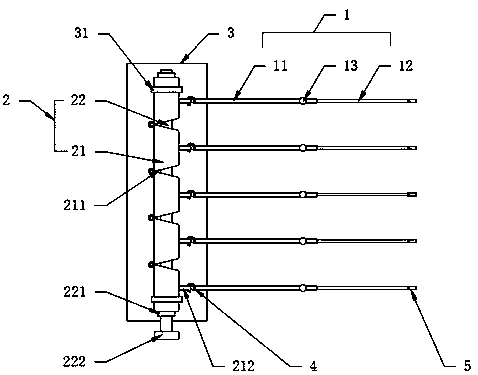
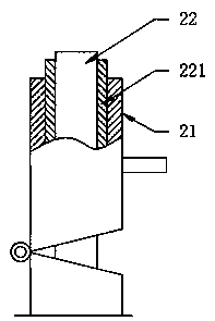
[0036] see Figure 1-5 , a muscle retraction device for general surgery, comprising a telescopic hanging rod 1, an arched retraction tube set 2 and a support compensation frame 3, the arched retraction tube set 2 includes at least three traction tubes 21 hinged from head to tail and Through the driving flexible shaft 22 sleeved on the three traction tubes 21, the opposite ends of the two adjacent traction tubes 21 are provided with matching slopes 211, wherein the hinge points of the adjacent traction tubes 21 are located on the side away from the matching slopes 211, Driven by the drive flexible shaft 22, a plurality of traction tubes 21 change from a straight line to an arched shape. The outer wall of the traction tubes 21 is detachably connected to one end of the telescopic hanging rod 1, and the telescopic hanging rod 1 is far away from the arch. One end of the opening tube group 2 is fixedly provided with a traction hook 5, that is to say, after the traction hook 5 is con...

Embodiment 2

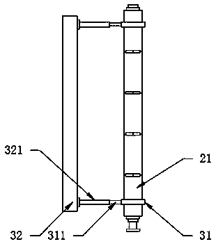
[0038] see figure 2 , with respect to the further description of Embodiment 1, the outer wall of the sliding sleeve 31 is fixedly provided with a circular shaft 311, the support compensation frame 3 is provided with a mounting plate 32, and the upper end surface of the mounting plate 32 is fixedly provided with a rotating shaft 311 The positioning sleeve 321 and the sliding sleeve 31 can be rotated to cope with the rotation of the traction tube 21, and at the same time can keep the traction tube 21 and the sliding sleeve 31 in sliding fit all the time to improve the stability of traction.

Embodiment 3

[0040] see figure 1 , with respect to the further description of Embodiment 1, the outer wall of the traction tube 21 is fixedly provided with a hanging ring 212, and one end of the telescopic hanging rod 1 is fixedly provided with a hook 4, thus, the telescopic hanging rod 1 and different Hook 4 is connected, can change the shape that muscle is pulled away.


PUM


Abstract

The invention discloses a muscle retractor for general surgery operation. The muscle retractor comprises a telescopic hanging rod, an arched retraction tube group and a support compensation frame, andis characterized in that the arched retraction tube group comprises at least three traction tubes which are hinged end to end and a driving flexible shaft which sleeves the at least three traction tubes in a penetrating manner. In the invention, the arched retraction tube group and the telescopic hanging rod are arranged, the arched retraction tube group comprises the at least three traction tubes which are hinged end to end and the driving flexible shaft which is arranged on the at least three traction tubes in a penetrating and sleeving mode, the opposite ends of every two adjacent tractiontubes are provided with matched slopes, and hinge points of the adjacent traction tubes are positioned on one side far away from the matched slopes; therefore, under the driving of the driving flexible shaft, the traction tubes are changed into arch shapes from straight line shapes, one sides of the traction tubes are connected with the telescopic hanging rod, the other end of the telescopic hanging rod is connected with muscle in a hanging mode through a traction hook, and the muscle can be stretched in an arc shape by rotating the driving flexible shaft; and the muscle retractor is simple in structure and convenient to operate.

Description

technical field [0001] The invention relates to the technical field of surgical muscle retraction equipment, in particular to a muscle retraction device for general surgery. Background technique [0002] With the development of the economy and the advancement of science and technology, medical facilities are gradually improving. Among them, the muscle retraction device for general surgery is one of the indispensable equipment in medical facilities. The existing device on the market already has Basic functions, but there are still deficiencies. [0003] At present, some common muscle retraction devices are usually a structure with multiple rollers winding wires. One end of the wire is provided with a traction hook, and the muscles are stretched by turning the rollers. , it needs to be equipped with multiple rollers, the mechanism is complicated, and the operation is inconvenient, so it is difficult to quickly achieve the purpose of muscle arc traction. [0004] Therefore, t...

Claims


Application Information

Patent Timeline
Patent Type & Authority Applications(China)
IPC IPC(8): A61B17/02
CPCA61B17/02
Inventor 周龙安王玲刘磊
Owner 周龙安
Learn More