Stirring equipment for production of non-dangerous chemicals

A technology of mixing equipment and chemicals, applied in mixer accessories, chemical instruments and methods, chemical/physical processes, etc., can solve the problems of vibration of the device, inconvenient cleaning of the inner wall of the device, affecting the production of chemicals, etc., to prevent splashing. Effect

Inactive Publication Date: 2020-04-07
徐州聚西廷新型材料科技有限公司
View PDF8 Cites 0 Cited by
  • Summary
  • Abstract
  • Description
  • Claims
  • Application Information

AI Technical Summary

Problems solved by technology

[0004] The purpose of the present invention is to provide a non-hazardous chemical production mixing equipment to solve the above background technology that the stirring shaft is inconvenient to disassemble during installation, which leads to inconvenient cleaning of the inner wall of the device, thus affecting the subsequent chemical production and installation of the device. It cannot be guaranteed to be placed stably, because the rotation of the motor and the stirring shaft causes the device to vibrate, which affects the stability of the device. When there are many chemicals in the mixing chamber, the rotation of the stirring shaft drives the chemicals to rotate through the liquid inlet pipe The problem of causing the chemicals in the container to flow out

Method used


Image

  • Stirring equipment for production of non-dangerous chemicals
  • Stirring equipment for production of non-dangerous chemicals
  • Stirring equipment for production of non-dangerous chemicals

Examples


Embodiment Construction

[0026] The following will clearly and completely describe the technical solutions in the embodiments of the present invention with reference to the accompanying drawings in the embodiments of the present invention. Obviously, the described embodiments are only some, not all, embodiments of the present invention. Based on the embodiments of the present invention, all other embodiments obtained by persons of ordinary skill in the art without making creative efforts belong to the protection scope of the present invention.

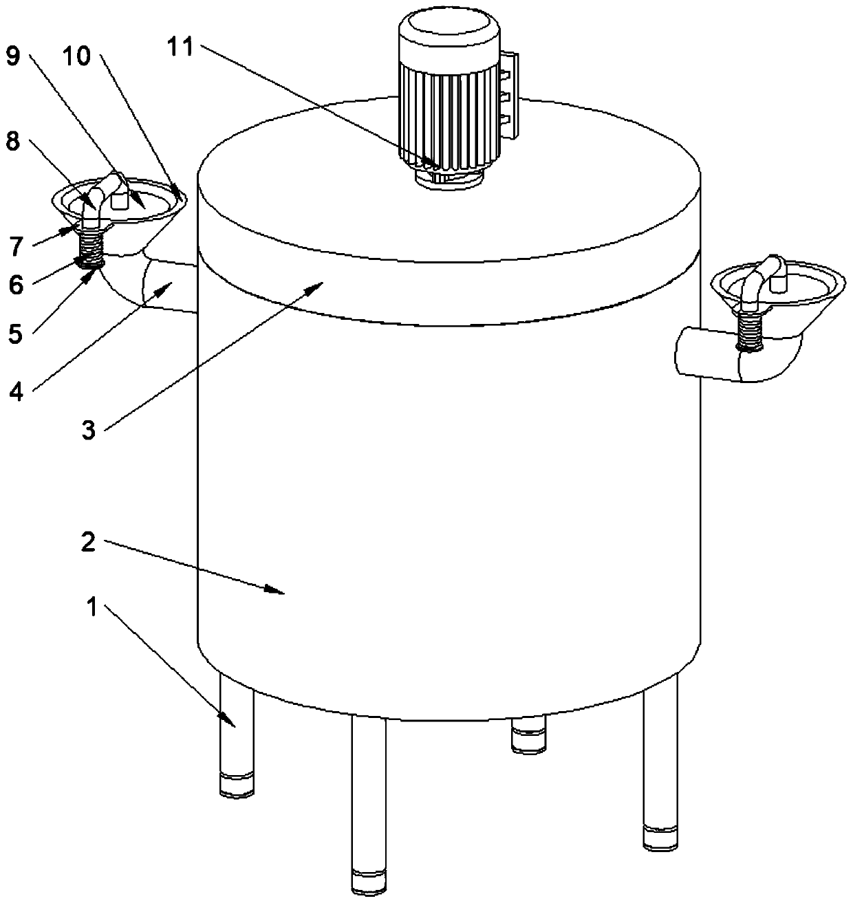
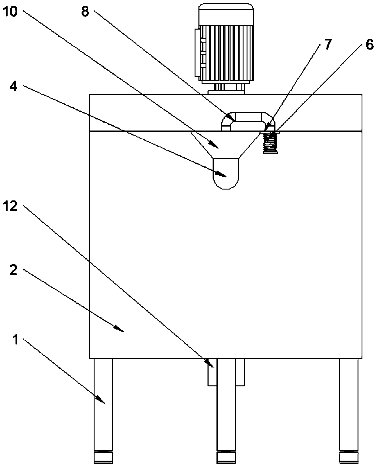
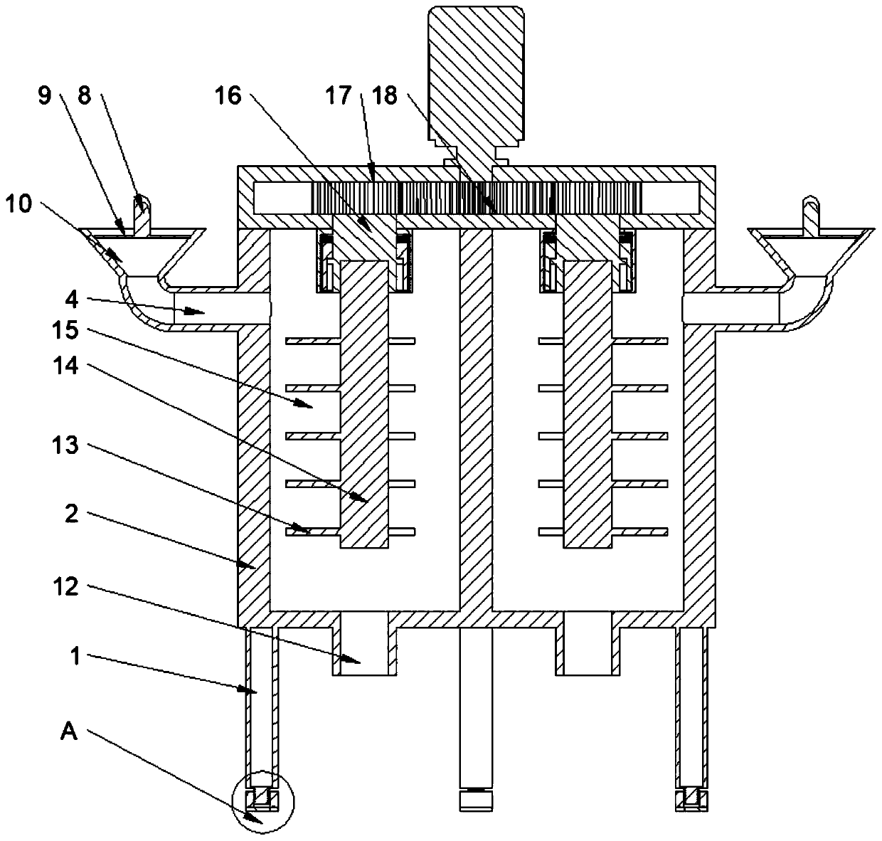
[0027] see Figure 1-Figure 6 , the present invention provides a technical solution: a non-hazardous chemical production mixing equipment, including a box body 2, a box cover 3, a rotating shaft 16, a connecting mechanism installed on the inner surface of the rotating shaft 16, and a connecting mechanism installed at the bottom of the box body 2 The adjustment mechanism and the shielding mechanism installed on the outer surface of the box body 2, the connectin...


PUM


Abstract

The invention discloses stirring equipment for production of non-dangerous chemicals. The stirring equipment comprises a box body, a box cover, a second rotating shaft, a connecting mechanism installed on the inner surface of the second rotating shaft, an adjusting mechanism installed at the bottom end of the box body, and a shielding mechanism installed on the outer surface of the box body. The connecting mechanism comprises a first rotating shaft, the first rotating shaft is fixedly connected to the bottom end surface of the second rotating shaft, and a second limiting plate is arranged on the outer surface of the top end of the second rotating shaft. The stirring equipment has the beneficial effects as follows: a clamping block mounted on the outer surface of the first rotating shaft and a pressing head connected with the clamping block are designed, and the clamping block can be easily clamped by the pressing head; a pressing ring connected with the outer surface of the pressing head is designed, and the pressing head can be easily clamped into the clamping block; a second sliding rail connected with a sliding groove in the inner surface of the pressing ring is designed, and itis guaranteed that the pressing ring does not rotate; a second rotating block in threaded connection with the pressing ring is designed, and sliding of the pressing ring is facilitated; and a secondlimiting plate located at the top end of the inner surface of the second rotating block is designed, and the position of the second rotating block can be easily fixed.

Description

technical field [0001] The invention belongs to the technical field of chemical production, and in particular relates to a non-hazardous chemical production stirring equipment. Background technique [0002] Chemicals are pure substances and mixtures of various elements, whether natural or man-made. Non-hazardous chemicals refer to chemicals that are not toxic, corrosive, explosive, flammable, or combustion-supporting, and are not harmful to the human body, facilities, or the environment. In the chemical production process, the stirring reaction equipment often used is generally a single stirring equipment, which includes a stirring chamber, and a stirring shaft is arranged in the stirring chamber, and the reaction liquid is sent into the inside of the stirring chamber through the liquid inlet, and the stirring shaft is used to stir the reaction. After the reaction is complete, it will be discharged from the discharge port. A device for forced convection and uniform mixing ...

Claims


Application Information

Patent Timeline
Patent Type & Authority Applications(China)
IPC IPC(8): B01F7/18
CPCB01F27/191B01F27/2322B01F27/90B01F35/181
Inventor 姚晓彤孙玉梅陈启潘梁宵刘威田亚
Owner 徐州聚西廷新型材料科技有限公司
Why Eureka
Try Eureka