Production equipment used for automatic snap-fit of dome assemblies

A production equipment and automatic buckle technology, applied in metal processing equipment, metal processing, manufacturing tools, etc., can solve problems such as excessive deformation of shrapnel, uneven quality, skin and epidermis damage, etc., to achieve accurate positioning, reliable action, and high efficiency. high effect

Pending Publication Date: 2019-06-07
中山市霍尔普自动化科技有限公司
View PDF0 Cites 0 Cited by
  • Summary
  • Abstract
  • Description
  • Claims
  • Application Information

AI Technical Summary

Problems solved by technology

[0004] In the traditional production process, the fastening of the upper conductive sheet 1 and the lower conductive sheet 2 can only be fastened by skilled workers using both hands to perform a multi-dimensional composite action. The deformation of the shrapnel is too large, resulting in uneven quality
In addition, after working for a long time, multiple knuckle joints of workers are prone to deformation, and the skin epidermis is repeatedly damaged. Therefore, it is imperative to realize the automation of this process.

Method used


Image

  • Production equipment used for automatic snap-fit of dome assemblies
  • Production equipment used for automatic snap-fit of dome assemblies
  • Production equipment used for automatic snap-fit of dome assemblies

Examples


Embodiment 1

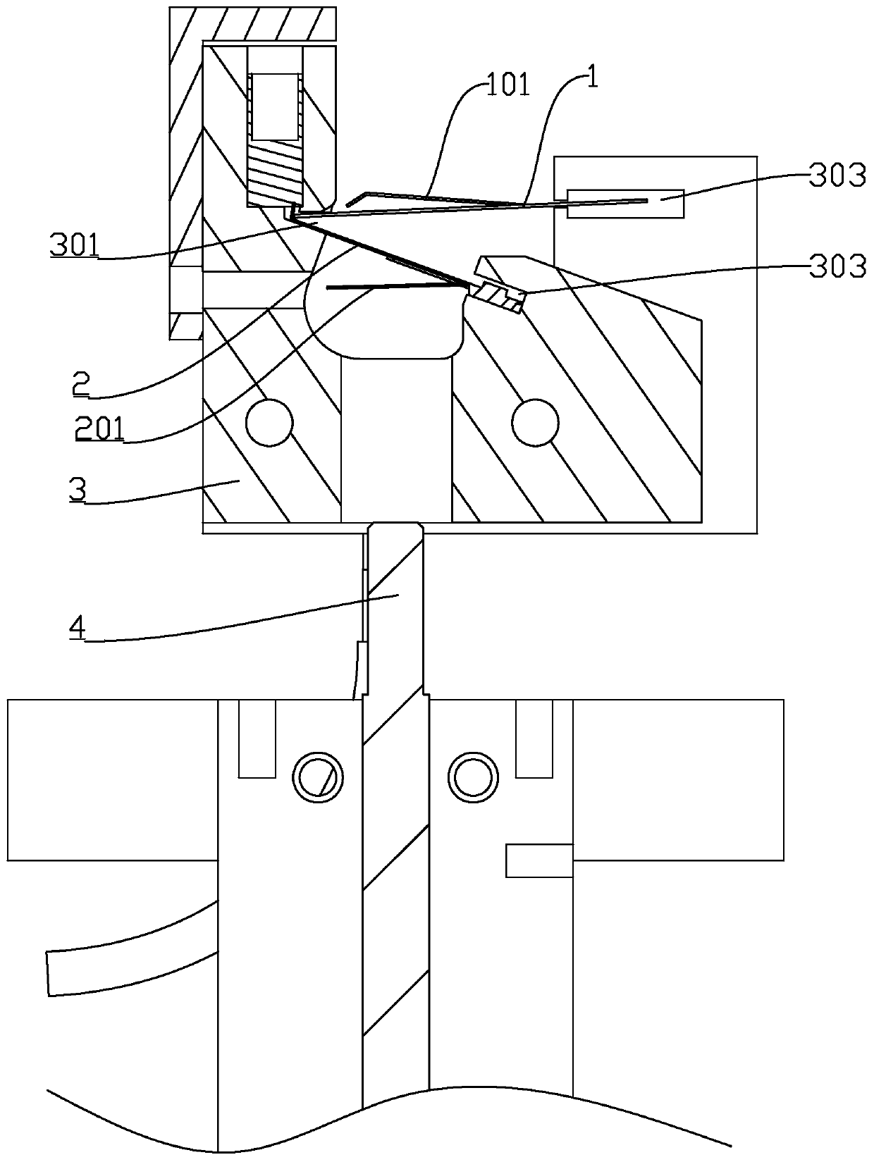
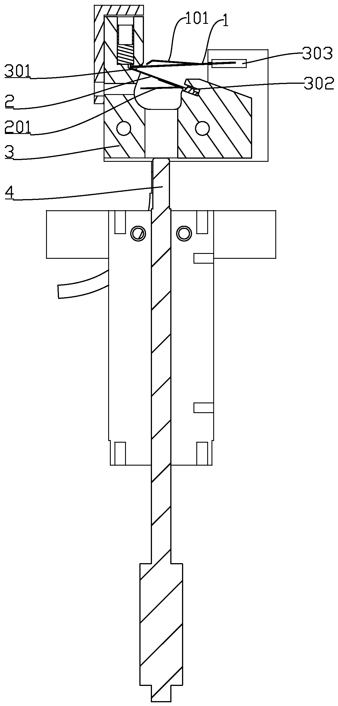
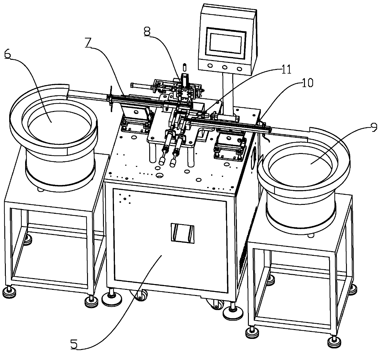
[0031] refer to Figure 1 to Figure 3 , this embodiment discloses a production equipment for automatic fastening of shrapnel components, which has a body 5, and the body 5 is provided with a pushing mechanism, a first clamping tool and a second clamping tool, and the first The clamping tool is provided with a first clamping end adapted to one end of the lower conductive sheet 2 away from the connection point of the energy storage elastic piece 201 and a second clamping end adapted to one end of the lower conductive sheet 2 close to the connection point of the energy storage elastic piece 201. The clamping end, the horizontal height of the first clamping end is higher than the second clamping end, so as to tilt it when clamping the lower conductive sheet 2, and the first clamping end is provided with the upper conductive sheet 1 The second clamping tool is located above the second clamping end, and is used to fix the upper conductive sheet 1 above the lower conductive sheet 2 w...

Embodiment 2

[0050] This embodiment takes Embodiment 1 as the main body, and its main difference is that the production equipment in this embodiment also includes a detection mechanism 12 for detecting whether the upper conductive sheet 1 and the lower conductive sheet 2 are fully engaged. Such as Figure 10 As shown, the detection mechanism 12 is located on the right side of the push rod 4, and the distance between the detection mechanism 12 and the push rod 4 is equal to the distance between the push rod 4 and the end of the channel 3, so as to facilitate the work of the pushing actuator.

[0051]Correspondingly, the body 5 is provided with two discharge ports at the end of the channel 3, and a flap is arranged between the two discharge ports, and the flap is driven by a cylinder or a motor so that the two discharge ports can be separated. Butt channel 3 ends. In this way, when the detection mechanism 12 detects whether the upper conductive sheet 1 and the lower conductive sheet 2 are f...

Embodiment 3

[0053] This embodiment takes Embodiment 1 as the main body, and its main difference is that the gripper 1103 in this embodiment is directly set at the end of the upper conductive sheet trough 1001, so that the upper conductive sheet 1 is directly sent into the gripper through the second vibrating mechanism 1002 Inside 1103. Afterwards, the upper conductive sheet 1 is directly inserted into the channel 3 through the jaws 1103 . In this embodiment, the introduction mechanism 11 does not need to be provided with a first pushing mechanism and a second pushing mechanism, and the structure is simpler.


PUM


Abstract

The invention discloses production equipment used for automatic snap-fit of dome assemblies. The production equipment is provided with a body. A pushing mechanism, a first clamping tooling and a second clamping tooling are arranged on the body. The first clamping tooling is provided with a first clamping end and a second clamping end which adapt to a lower conducting plate. The horizontal height of the first clamping end is larger than that of the second clamping end, and the first clamping end is provided with an insert port allowing an upper conducting plate to be inserted therein. The second clamping tooling is located above the second clamping end and used for fixing the upper conducting plate. The pushing mechanism is provided with a pushing rod located between the first clamping endand the second clamping end, and a first driving mechanism used for driving the pushing rod to rise and fall. When the production equipment is used for camping, one ends of the upper conducting plateand the lower conducting plate are attached, the other ends of the upper conducting plate and the lower conducting plate are open, the pushing rod can conveniently push the upper conducting plate andthe lower conducting plate to be snap-fitted into an elastic tongue piece, the snap-fitting procedure is completed, the structural design is reliable in action, positioning is precise, the productionquality is consistent, and the efficiency is remarkably higher than that of skilled workers.

Description

technical field [0001] The invention relates to the technical field of thermostat production equipment, in particular to a production equipment for automatic fastening of shrapnel components in a thermostat. Background technique [0002] Thermostats are widely used in various electrical equipment to control the temperature of heating / cooling. In addition to the temperature sensing element, the on-off shrapnel component is one of its core components, which is used to turn on or off Power-on connection requires high conductive overload capacity, and also requires sensitive contact action, long working life, and high ambient temperature. [0003] Shrapnel components include such as Figure 11 with Figure 12 In the upper conductive sheet 1 and the lower conductive sheet 2 shown, the upper conductive sheet 1 is provided with an upwardly tilted elastic tongue 101, and the lower conductive sheet 2 is provided with a downwardly tilted energy storage shrapnel 201, and the lower con...

Claims


Application Information

Patent Timeline
Patent Type & Authority Applications(China)
IPC IPC(8): B23P19/04B23P19/00
Inventor 朱运高
Owner 中山市霍尔普自动化科技有限公司
Why Eureka
Try Eureka