
Measuring device and measuring method

A technology of measuring device and measuring method, which is applied in the directions of measuring device, optical instrument testing, testing optical fiber/optical waveguide equipment, etc., can solve the problems of decreased operation efficiency and insufficient consideration, and achieve the effect of improving operation efficiency

Pending Publication Date: 2020-03-31
YOKOGAWA ELECTRIC CORP +1
View PDF11 Cites 0 Cited by
  • Summary
  • Abstract
  • Description
  • Claims
  • Application Information

AI Technical Summary

Problems solved by technology

As a result, work efficiency is reduced
In Patent Document 1, such problems are not sufficiently considered

Method used

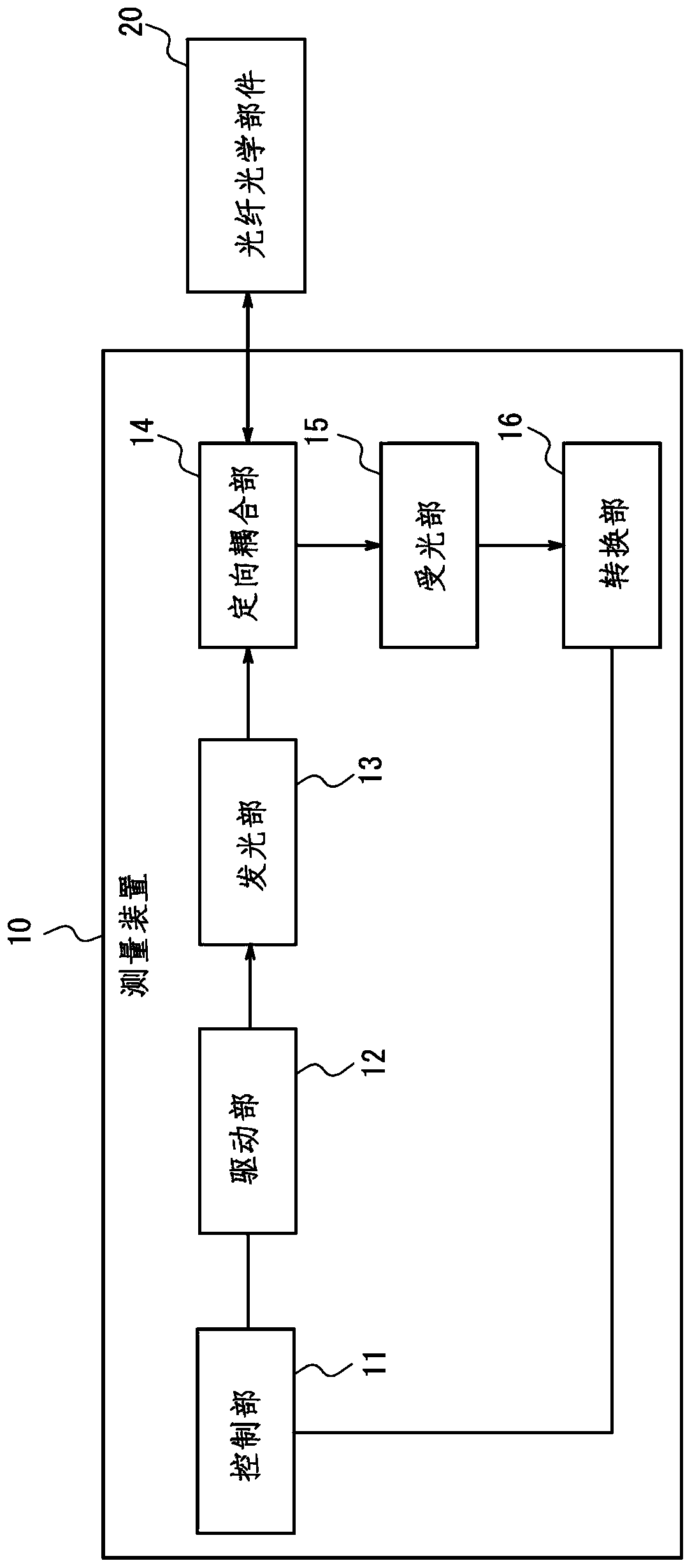
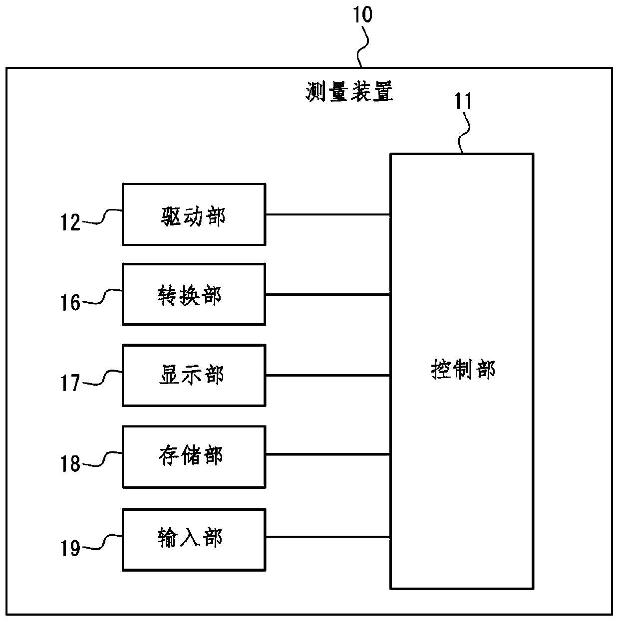
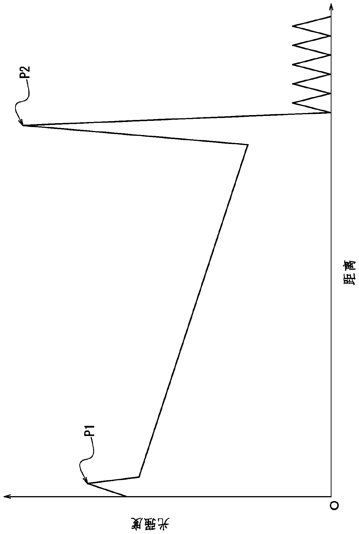

Image

  • Measuring device and measuring method
  • Measuring device and measuring method
  • Measuring device and measuring method

Examples


Embodiment Construction

[0040] The background and problems of the prior art are described in detail.

[0041] In the optical communication system, when laying the optical fiber as its communication medium or during the maintenance after laying, OTDR is used to confirm whether the laying work is good, to search for the fault point of the optical fiber, and to measure the optical loss of the fault point. Wait. The measurement devices in the OTDR that measure the optical loss of the optical fiber and the distance to the fault point are roughly divided into two types: averaging measurement and real-time measurement. "Average measurement" means, for example, a measurement that is averaged over a period of several seconds or more or a certain number of times of addition. "Real-time measurement" means, for example, measurement in which the updating speed of the screen display is increased by performing averaging in a short time or a small number of addition calculations of 1 second or less.

[0042]For ex...


PUM


Abstract

A measuring device and a measuring method are provided. The measuring device (10) includes a light emitting unit (13) that irradiates pulsed light coupled with a fiber optic component (20) adopted asan object to be measured; a light receiving unit (15) that detects light to be measured, the light to be measured being generated by pulse light irradiated by the light emitting unit (13) and propagating in a direction opposite to the propagating direction of the pulse light; and a control unit (11) that calculates a parameter related to the fiber optic component (20) based on the detection signalof the light to be measured detected by the light receiving unit (15). The control unit (11) determines whether the parameter calculated exceeds a predetermined threshold, and reduces the average intensity of the pulsed light when the calculated parameter exceeds the predetermined threshold.

Description

[0001] Cross References to Related Applications [0002] This application claims priority from Japanese Patent Application No. 2018-179049 filed with the Japan Patent Office on September 25, 2018, and the entire disclosure of this application is incorporated herein by reference. technical field [0003] The invention relates to a measuring device and a measuring method. Background technique [0004] Conventionally, in fiber optic components including optical fibers, there is known a technique related to a measuring device that searches for a fault point of the fiber optic component, measures light loss at the fault point, and the like. [0005] For example, Patent Document 1 discloses an optical pulse test device that can shorten and reduce the time for the user to perform measurement and monitoring of an OTDR (Optical Time Domain Reflectometer) when confirming the fusion splicing and splicing of optical fibers . [0006] prior art literature [0007] Patent Document 1: J...

Claims


Application Information

Patent Timeline
Patent Type & Authority Applications(China)
IPC IPC(8): G01M11/00
CPCG01M11/3118G01M11/3154
Inventor 青木省一
Owner YOKOGAWA ELECTRIC CORP
Learn More