
Rare Earth Halide Scintillator Materials

A scintillation material and halide technology, applied in the directions of luminescent materials, polycrystalline material growth, chemical instruments and methods, etc., can solve the problems of crystal growth defects, affecting the uniformity of crystal performance, inconsistent doping concentration, etc., to improve the yield Effect

Active Publication Date: 2022-02-22
GRIREM ADVANCED MATERIALS CO LTD +2
View PDF5 Cites 0 Cited by
  • Summary
  • Abstract
  • Description
  • Claims
  • Application Information

AI Technical Summary

Problems solved by technology

However, alkaline earth metal ions are heterogeneous impurities after all, and there are differences in radius and valence between rare earth ions. This kind of doping is easy to cause crystal growth defects, and will cause the doping concentration of alkaline earth metal ions in different parts of the crystal due to segregation. Inconsistency, which affects the uniformity of crystal properties

Method used


Image

  • Rare Earth Halide Scintillator Materials

Examples


Embodiment 1

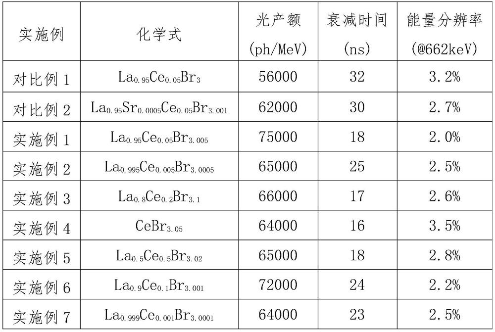
[0036] Embodiment 1: Accurately weigh 119.89g anhydrous LaBr in the Ar glove box 3 (99.99%) and 6.46g anhydrous CeBr 3.1 (99.99%), after mixing evenly, pack into a quartz crucible with a diameter of 25mm. The rest of the operations are the same as in Comparative Example 1.

[0037] Embodiment 2-7 except that raw material proportioning is different, all the other operations are the same as embodiment 1.

[0038] The detailed comparative situation of all embodiments is shown in Table 1.

[0039] Table 1

[0040]

[0041] In summary, the present invention provides a rare earth halide scintillation material, the general chemical formula of which is La 1- x Ce x Br 3+y , where 0.001≤x≤1, 0.0001≤y≤0.1. The rare earth halide scintillation material obtained by the present invention has excellent scintillation performance, and its overall performance is obviously better than that of conventional undoped lanthanum bromide crystals, and its crystal uniformity is obviously bett...


PUM

PropertyMeasurementUnit
lengthaaaaaaaaaa

Abstract

The invention relates to a rare earth halide scintillation material, the general chemical formula of which is La 1‑x Ce x Br 3+y , where 0.001≤x≤1, 0.0001≤y≤0.1. The rare earth halide scintillation material involved in the present invention has excellent scintillation properties such as high light output, high energy resolution, and fast decay.

Description

technical field [0001] The invention relates to the field of inorganic scintillating materials, in particular to a rare earth halide scintillating material. Background technique [0002] Scintillation materials can be used to detect high-energy rays such as α-rays, γ-rays, and X-rays, and high-energy particles such as neutrons, and are widely used in nuclear medicine, high-energy physics, safety inspection, oil logging and other fields. [0003] Scintillation materials are usually applied in the form of single crystals, and in some cases can also be ceramics or other forms. [0004] Different application fields have different performance requirements for scintillation materials. However, for most applications, scintillation materials are expected to have as high a light yield as possible, as short a decay time as possible, and as high an energy resolution as possible. Especially for nuclear medicine imaging devices such as positron emission tomography (PET) scanners, these...

Claims


Application Information

Patent Timeline
Patent Type & Authority Patents(China)
IPC IPC(8): C30B29/12C30B11/02C09K11/85G01T1/202
CPCC30B29/12C30B11/02C09K11/7772G01T1/2023C01F17/253C01P2002/54G01T1/202G01T1/362
Inventor 余金秋罗亮刁成鹏崔磊吴浩何华强
Owner GRIREM ADVANCED MATERIALS CO LTD
Learn More