
Feeding and discharging device

A technology of mounting plate and reclaiming mechanism, which is applied in the direction of conveyor control device, transportation and packaging, conveyor, etc., can solve the problems that affect the loading and unloading speed, affect the efficiency of equipment, and cannot realize the smooth transition process, so as to improve efficiency, Improve the coherence of movement and the effect of simple structure

Pending Publication Date: 2020-03-31
珠海市梅木自动化科技有限公司
View PDF0 Cites 7 Cited by
  • Summary
  • Abstract
  • Description
  • Claims
  • Application Information

AI Technical Summary

Problems solved by technology

In this way, there will be a situation. After the material completes one action, it needs to wait for a certain period of time before performing another action. The smooth transition process cannot be achieved between the two actions, which affects the speed of loading and unloading, and then affects the entire equipment. s efficiency

Method used


Image

  • Feeding and discharging device
  • Feeding and discharging device
  • Feeding and discharging device

Examples


Embodiment Construction

[0025] Embodiments of the present invention are described in detail below, examples of which are shown in the drawings, wherein the same or similar reference numerals designate the same or similar elements or elements having the same or similar functions throughout. The embodiments described below by referring to the figures are exemplary only for explaining the present invention and should not be construed as limiting the present invention.

[0026] In the description of the present invention, it should be understood that the orientation descriptions, such as up, down, front, back, left, right, etc. indicated orientations or positional relationships are based on the orientations or positional relationships shown in the drawings, and are only In order to facilitate the description of the present invention and simplify the description, it does not indicate or imply that the device or element referred to must have a specific orientation, be constructed and operated in a specific ...


PUM


Abstract

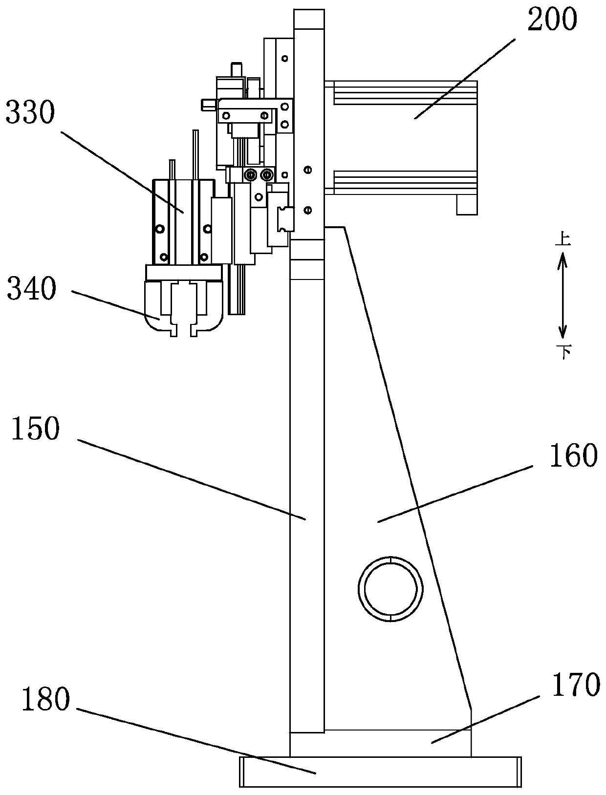
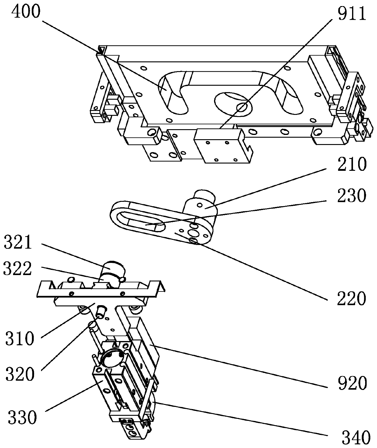
The invention relates to the technical field of automation and discloses a feeding and discharging device. The feeding and discharging device comprises a base, a moving mechanism, a material fetchingmechanism and a drive mechanism. An n-shaped sliding groove is formed in the side face of the base. The moving mechanism is a double-axis sliding rail. The material fetching mechanism is installed onthe moving mechanism and provided with a connection rod connected with the n-shaped sliding groove. The driving mechanism comprises a drive shaft. The drive shaft is provided with a linkage. The linkage is connected with the connection rod and drives the material fetching mechanism to move along the n-shaped sliding groove. According to the feeding and discharging device, the n-shaped sliding groove structure is designed, lifting and transverse movement are linked into one action, the heights of the material fetching position and material placing position are controlled through flexible operation, and a height difference is avoided; compared with a traditional double-axis moving device, the feeding and discharging device reduces one drive device, so that the efficiency of equipment is improved, the mechanism is simplified, and the coherence of lifting action and transverse movement action is improved, and the cost of the equipment is greatly lowered.

Description

technical field [0001] The invention relates to the technical field of automation equipment, in particular to a loading and unloading device. Background technique [0002] In the field of automation equipment, in order to realize the moving process of materials on a plane, it is usually necessary to use two slide rails or cylinders arranged along the direction of the plane coordinate system to realize the loading and unloading process of materials, such as the first cylinder or the first slide rail. For lifting materials, the second cylinder or the second slide rail is used to traverse the materials. In this way, there will be a situation. After the material completes one action, it needs to wait for a certain period of time before performing another action. The smooth transition process cannot be achieved between the two actions, which affects the speed of loading and unloading, and then affects the entire equipment. s efficiency. Over the years, automation equipment has ...

Claims


Application Information

Patent Timeline
Patent Type & Authority Applications(China)
IPC IPC(8): B65G47/90B65G43/00
CPCB65G47/901B65G43/00B65G2203/042
Inventor 杨宏斌李流新陈庆强
Owner 珠海市梅木自动化科技有限公司
Learn More