A Camera Time Synchronization System Based on LED Light

A technology for LED lights and cameras, applied in the field of camera timing systems based on LED lights, can solve the problems of stroboscopic, invisible, low brightness, etc., and achieve the effect of reducing the area of ​​​​the field of view, accurate timing, and high brightness

Active Publication Date: 2020-10-30
INST OF GEOLOGY CHINA EARTHQUAKE ADMINISTRATION
View PDF7 Cites 0 Cited by
  • Summary
  • Abstract
  • Description
  • Claims
  • Application Information

AI Technical Summary

Problems solved by technology

The disadvantages of this method are: 1) poor compatibility, the external trigger interface and voltage of various cameras may be different, every time a new camera is added, it is necessary to design or purchase a corresponding trigger cable and convert the voltage; The time difference is still unknown and uncontrollable. Different cameras have different reaction times to trigger signals. The reaction time is limited by the type and manufacturer of the camera and cannot be controlled by the user; and because the shutter time of different cameras varies greatly, camera manufacturers The design is only based on the performance requirements of its own camera, which leads to a large difference in the reaction time of different types of cameras to trigger signals (can be as large as several orders of magnitude), which greatly affects the timing quality between low-speed and high-speed cameras; 3) There are very few time points that can be used for time synchronization. The external trigger signal is used to control the camera, and the first electric pulse in the trigger signal is often used to start continuous photographing, so there is only one time point between each camera; a few cameras ( Low-speed cameras and some high-speed cameras) can use an external trigger signal to trigger each shutter action (that is, take pictures), but it is difficult for cameras with different speeds to share the same pulse signal. For example, high-speed cameras use 5kHz periodic pulse signals, and such high-speed signals , can not be normally responded by low-speed cameras
However, under the existing conditions, this idea is not convenient or even available
Because triggering a certain physical signal often requires manual operation, which will introduce errors and instability; clocks based on hands have poor stability at kilohertz and megahertz speeds, and are not suitable for high-speed time synchronization; existing electronic Although the clock has relatively good stability, it also has disadvantages: 1) the brightness is very low, and it is almost invisible under the condition of a very short shutter time of a high-speed camera; 2) there is a strobe, and the general electronic clock is designed for When viewed by the human eye, the stroboscopic flicker of tens of hertz does not affect the human eye. Can not provide useful signals; 3) Ordinary electronic clocks cannot provide high-precision and resolution signals above kilohertz; 4) Ordinary electronic clocks are too large. It is possible to reduce the viewing area, and the area of ​​an ordinary electronic clock (a few centimeters by a few centimeters) is much larger than the viewing area that a high-speed camera can provide for time synchronization

Method used


Image

  • A Camera Time Synchronization System Based on LED Light
  • A Camera Time Synchronization System Based on LED Light

Examples


Embodiment Construction

[0026] The following will clearly and completely describe the technical solutions in the embodiments of the present invention with reference to the accompanying drawings in the embodiments of the present invention. Obviously, the described embodiments are only some, not all, embodiments of the present invention. Based on the embodiments of the present invention, all other embodiments obtained by persons of ordinary skill in the art without making creative efforts belong to the protection scope of the present invention.

[0027] The purpose of the present invention is to provide a camera time synchronization system based on LED lamps, which realizes accurate time synchronization among multiple cameras.

[0028] In order to make the above objects, features and advantages of the present invention more comprehensible, the present invention will be further described in detail below in conjunction with the accompanying drawings and specific embodiments.

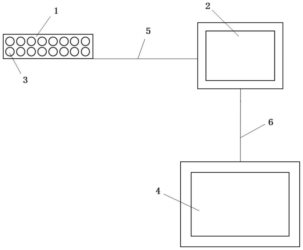
[0029] figure 1 The struct...


PUM


Abstract

The invention relates to a camera synchronization system based on an LED lamp. The time synchronization system comprises an LED time synchronization lamp panel and a controller. The LED time synchronization lamp panel comprises a plurality of LED lamps, and the output end of the controller is connected with the control ends of the LED lamps through control data lines. The controller is used for generating non-stroboscopic pulse signals with different frequencies, transmitting the non-stroboscopic pulse signals to the plurality of LED lamps through the control data lines and controlling the states of the plurality of LED lamps; and the plurality of cameras shoot the LED time synchronization lamp panel at the same time and are used for realizing time calibration during image processing. According to the invention, the controller controls the LED timing lamp panel to display a stroboflash-free signal with a specific frequency; the phenomenon of flickering is avoided; and the shape of theLED time tick lamp panel can be flexibly designed, the visual field area of the cameras is reduced as much as possible by the LED time tick lamp panel, and the LED lamps of the LED time tick lamp panel are high in brightness, so that the cameras can shoot high-precision and high-resolution signals, and accurate time tick among the multiple cameras is realized.

Description

technical field [0001] The invention relates to the field of digital image processing, in particular to a camera time synchronization system based on LED lights. Background technique [0002] Compared with other sensors, digital images have the advantages of intuition, more observation points (for cameras, the number of pixels is the number of observation points), rapid technological progress, and mature technology. Therefore, in recent years, cameras, high-speed cameras, and thermal infrared cameras have been used as observation points. The means have been widely used in scientific experimental research and engineering technology applications. However, different kinds of cameras have their own advantages. For example, ordinary commercial cameras are slow in speed (one frame in a few seconds to one frame in several hertz), but have a high number of pixels (millions of pixels) and can shoot continuously for a long time at low speed; high-speed cameras have a shooting speed (...

Claims


Application Information

Patent Timeline
Patent Type & Authority Patents(China)
IPC IPC(8): G04G5/00G04G7/00
CPCG04G5/00G04G7/00
Inventor 汲云涛齐文博刘力强
Owner INST OF GEOLOGY CHINA EARTHQUAKE ADMINISTRATION
Why Eureka
Try Eureka