
Coating layer stripping equipment and coating layer stripping method

A technology of coating layer and equipment, applied in the direction of light guide, optics, instrument, etc., can solve the problem of insufficient flatness of the section

Pending Publication Date: 2020-03-27
GZ PHOTONICS CO LTD
View PDF0 Cites 4 Cited by
  • Summary
  • Abstract
  • Description
  • Claims
  • Application Information

AI Technical Summary

Problems solved by technology

[0004] Based on this, it is necessary to provide a kind of coating stripping equipment and coating layer for the existing coating layer stripping equipment to provide a coating stripping equipment and coating layer Stripping method

Method used


Image

  • Coating layer stripping equipment and coating layer stripping method
  • Coating layer stripping equipment and coating layer stripping method
  • Coating layer stripping equipment and coating layer stripping method

Examples


Embodiment Construction

[0030] In order to facilitate the understanding of the present invention, the following will describe the present invention more fully. However, the present invention can be embodied in many different forms and is not limited to the embodiments described herein. On the contrary, these embodiments are provided to make the understanding of the disclosure of the present invention more thorough and comprehensive.

[0031] Unless otherwise defined, all technical and scientific terms used herein have the same meaning as commonly understood by one of ordinary skill in the technical field of the invention. The terms used herein in the description of the present invention are for the purpose of describing specific embodiments only, and are not intended to limit the present invention.

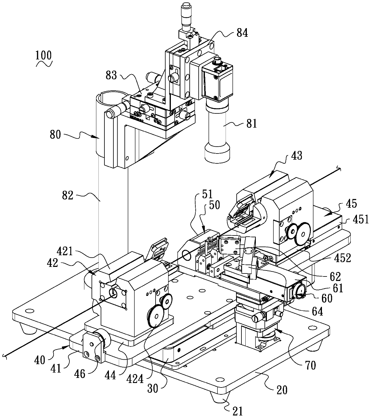
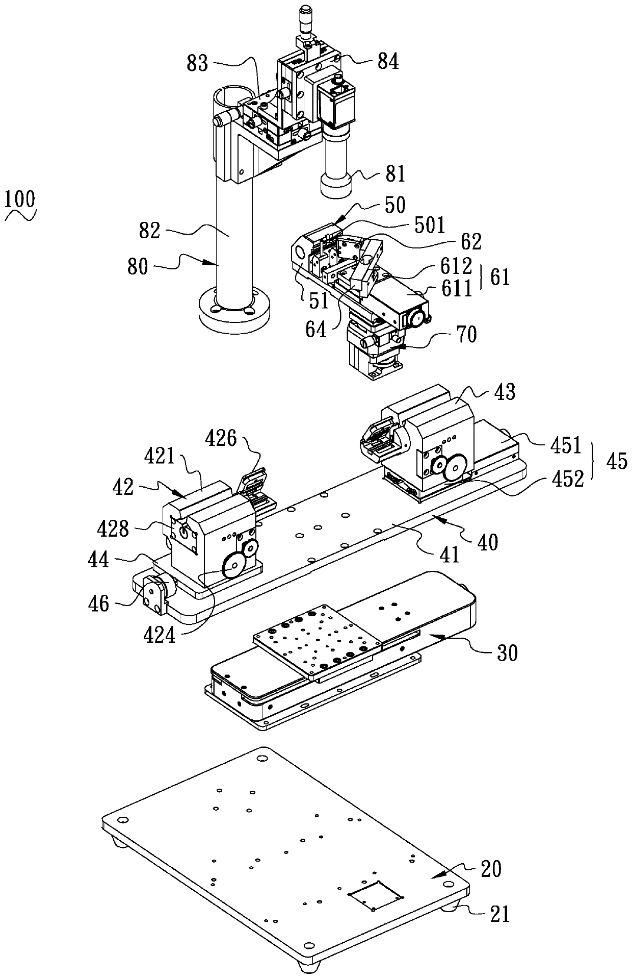
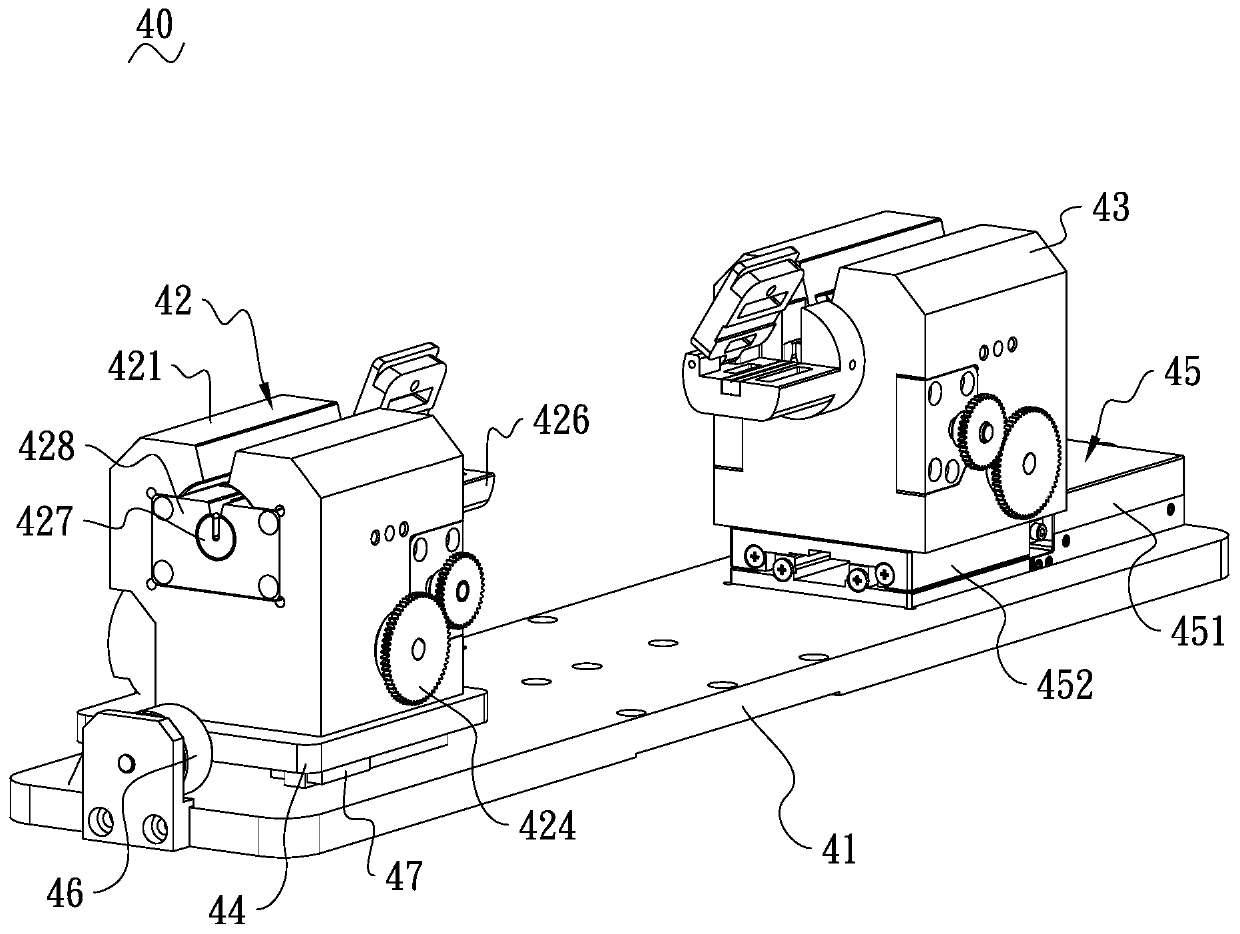
[0032] see Figure 1 to Figure 9 , is a coating layer stripping device 100 according to an embodiment of the present invention, which is used to strip the coating layer of an optical fiber, and the rem...


PUM


Abstract

The invention discloses coating layer stripping equipment and a coating layer stripping method. The coating layer stripping equipment comprises a bottom plate, an axial moving mechanism mounted on thebottom plate, an optical fiber rotating mechanism mounted on the axial moving mechanism, an optical fiber positioning mechanism for supporting an optical fiber, and a cutting mechanism arranged on the bottom plate, the optical fiber rotating mechanism comprises an axial base plate connected with the axial moving mechanism, a first rotating assembly arranged on the axial base plate and a second rotating assembly arranged on the axial base plate; the first rotating assembly and the second rotating assembly are respectively used for clamping the optical fiber; the first rotating assembly and thesecond rotating assembly are also used for synchronously driving the optical fiber to rotate; and the cutting mechanism and the optical fiber positioning mechanism are correspondingly arranged, so that the section left after the coating layer is stripped is smooth and flat, and the cladding light filtering effect is improved.

Description

technical field [0001] The invention relates to optical fiber processing equipment, in particular to a coating layer stripping equipment and a coating layer stripping method. Background technique [0002] Optical transmission technology refers to the use of the principle of total reflection to transmit light in fibers made of glass. Usually, in the steps of preparing optical fiber, the necessary steps to be carried out are to add a pre-coating layer to the bare optical fiber for protection, to isolate the external moisture, increase the mechanical strength of the optical fiber, prevent the bending loss of the optical fiber caused by external force, and prolong the life of the optical fiber. How long to use. In order to improve the beam quality of the fiber laser, it is necessary to strip the high-order mode components of the signal light and the unabsorbed pump light generated when the pump light is transmitted in the fiber from the fiber. Therefore, the middle part of the ...

Claims


Application Information

Patent Timeline
Patent Type & Authority Applications(China)
IPC IPC(8): G02B6/245
CPCG02B6/245
Inventor 蒲慧慧王维金梦马修泉
Owner GZ PHOTONICS CO LTD
Learn More