
Bottle body transfer device

A conveying device and bottle technology, applied in packaging, conveyors, conveyor objects, etc., can solve problems such as bottle skew, and achieve the effect of avoiding skew and ensuring bottle quality.

Active Publication Date: 2020-03-27
重庆德立玻璃制品有限公司
View PDF10 Cites 3 Cited by
  • Summary
  • Abstract
  • Description
  • Claims
  • Application Information

AI Technical Summary

Problems solved by technology

[0003] The present invention intends to provide a bottle body conveying device to solve the technical problem that the bottle body tends to be skewed when the bottle body is pushed down in the prior art

Method used


Image

  • Bottle body transfer device
  • Bottle body transfer device
  • Bottle body transfer device

Examples


Embodiment 1

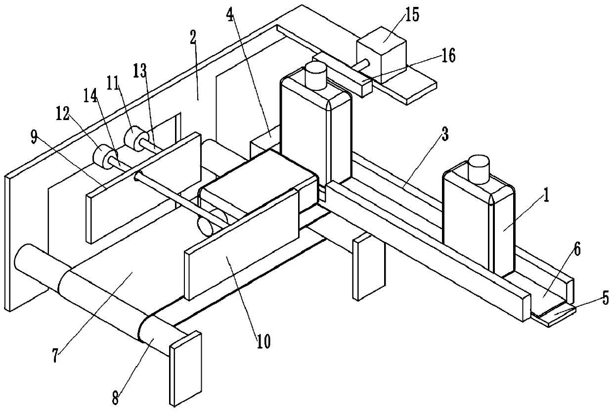
[0031] as attached figure 1 Shown: a bottle conveying device, including a frame 2, a first conveying unit and a second conveying unit, the first conveying unit is a conveying rail, the conveying rail includes an outer frame and a first conveyor belt 6, and the outer frame includes a stopper at the left end Plate 4 and the limit plate 3 on both sides, the baffle plate 4 and the limit plate 3 are fixed by bolts, the limit plate 3 is provided with a gap for transferring the bottle body; A first conveying roller (not shown in the figure), the first conveying roller is positioned between two spacer plates 3, and the first conveying belt 6 is tightened on the first conveying roller; One side of the first conveying roller is provided with for The first motor (not shown) that drives the first transmission roller to rotate, the first motor is fixed to the frame 2 by bolts, the output shaft of the first motor is fixed to the first transmission roller; A first support plate 5 for provid...

Embodiment 2

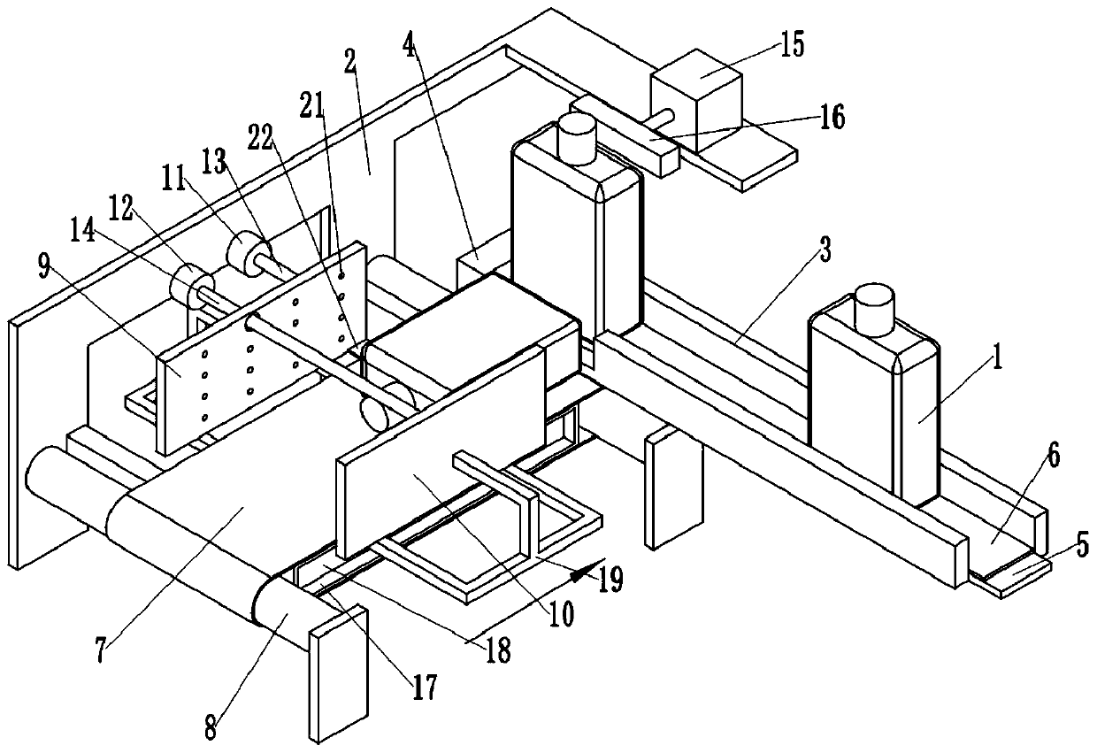
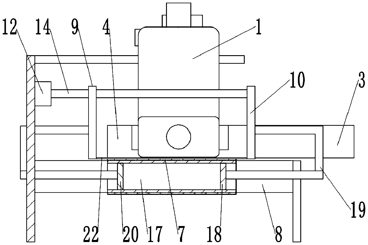
[0036] Such as figure 2 As shown, the difference between this embodiment and Embodiment 1 is that the frame 2 is fixedly connected with a sealed box 17 by bolts, and the sealed box 17 is located in the closed area formed by the second conveyor belt 7, and as image 3As shown, the upper surface of the sealing box 17 is flush with the lower surface of the second conveyor belt 7 . A first piston 20 and a second piston 18 are slidably connected in the sealing box 17, and the first piston 20 and the second piston 18 are arranged oppositely. The sealing box 17, the first piston 20 and the second piston 18 jointly form a sealed space. The arrangement of the first piston 20 and the second piston 18 is the same, here the first piston 20 is taken as an example for illustration, as image 3 As shown, the left end of the first piston 20 is welded and fixed with a connecting rod 19, and the upper end of the connecting rod 19 is fixed with the first slide block 9 by bolts; the first slide...


PUM


Abstract

The invention relates to the technical field of transfer devices and discloses a bottle body transfer device. The bottle body transfer device comprises a rack, a first transfer unit and a second transfer unit. Both the first transfer unit and the second transfer unit are rotatably connected to the rack, a direction adjusting and straightening mechanism is also arranged on one side of the second transfer unit, the direction adjusting and straightening mechanism comprises a limiting slide block which limits and adjusts the direction of a bottle body and a driving part for driving the limiting slide block, the limiting slide block comprises a first slide block and a second slide block, the first slide block and the second slide block are arranged on two sides of the second transfer unit in amirror image manner, and the first slide block and the second slide block are slidably arranged on the rack in opposite directions. By adopting the scheme, the technical problem that in the prior art,the bottle body which is pushed over is easy to skew can be solved.

Description

technical field [0001] The invention relates to the technical field of conveying devices, in particular to a bottle conveying device. Background technique [0002] The transfer process of bottle decals is divided into two parts, including the first transfer unit and the second transfer unit. The first transfer unit automatically transfers the bottles to the processing station for decals in batches, where the bottles are in an upright state Transportation is beneficial to make bottle feeding more convenient; however, when decaling, the bottle is required to be in an upside-down position to facilitate the processing of decals on the bottle, so it is necessary to set up a second transfer unit to transport the upside-down bottle, and A push-down mechanism needs to be set between the first transfer unit and the second transfer unit to push down the erected bottles. The current push-down mechanism mainly includes a cylinder and a swing arm. When the cylinder is running, it drives...

Claims


Application Information

Patent Timeline
IPC IPC(8): B65C9/02B65G47/24B65G47/22B65G47/57B65G23/04B65G23/22
CPCB65C9/02B65G23/04B65G23/22B65G47/22B65G47/24B65G47/57B65G2201/0244
Inventor 高青林
Owner 重庆德立玻璃制品有限公司
Learn More