
A control circuit and reducer control box of a tw-2 hump system reducer

A system reducer and control circuit technology, applied in the field of rail transit, can solve the problems of inability to achieve double power supply, large relay footprint, inconvenient on-site maintenance, etc., achieving a small footprint, convenient on-site maintenance, and less wiring. Effect

Active Publication Date: 2020-09-29
CRSC RESEARCH & DESIGN INSTITUTE GROUP CO LTD +1
View PDF6 Cites 0 Cited by
  • Summary
  • Abstract
  • Description
  • Claims
  • Application Information

AI Technical Summary

Problems solved by technology

When implemented on site, the relay occupies a large space, engineering wiring is required between the relay combinations, the construction workload is large, and it is not convenient for on-site maintenance. At the same time, the drive output of the microcomputer is a single-side output, and it is impossible to realize double-break of the power supply in case of failure.

Method used


Image

  • A control circuit and reducer control box of a tw-2 hump system reducer
  • A control circuit and reducer control box of a tw-2 hump system reducer
  • A control circuit and reducer control box of a tw-2 hump system reducer

Examples


Embodiment Construction

[0048] In order to make the purpose, technical solutions and advantages of the embodiments of the present invention more clear, the technical solutions in the embodiments of the present invention will be clearly and completely described below in conjunction with the accompanying drawings in the embodiments of the present invention. Obviously, the described embodiments It is a part of embodiments of the present invention, but not all embodiments. Based on the embodiments of the present invention, all other embodiments obtained by persons of ordinary skill in the art without making creative efforts belong to the protection scope of the present invention.

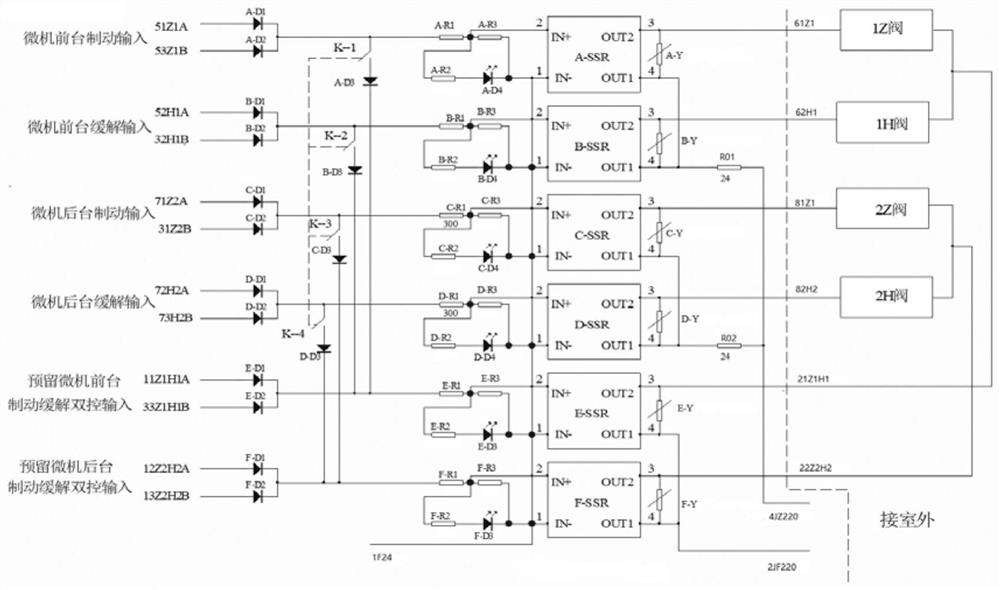
[0049] The present invention proposes a control circuit of a TW-2 hump system reducer, exemplary, such as figure 1 As shown, the control circuit includes a first control circuit and a second control circuit, wherein the first control circuit is connected to the front and rear reducers, and is used to control the front and rear...


PUM


Abstract

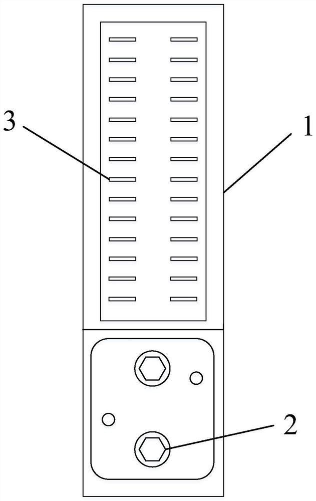
The invention belongs to the technical field of rail transit, and particularly relates to a control circuit of a TW-2 hump system speed reducer and a speed reducer control box. The control circuit comprises a first control circuit and a second control circuit, and the first control circuit is connected with a front-stage speed reducer and a back-stage speed reducer and used for controlling the front-stage speed reducer and the back-stage speed reducer to execute braking or relieving action; and the second control circuit is connected with the front-stage speed reducer, the back-stage speed reducer and the first control circuit and is used as a control loop of the front-stage speed reducer and the back-stage speed reducer so as to realize double control of the speed reducers. The speed reducer control box is installed on an indoor relay combination, the four operations of foreground braking, background braking, foreground relieving and background relieving of a speed reducer are controlled in a centralized mode, meanwhile, negative electricity generated when the speed reducer works is led into a control loop line, and double-break of a power source in the control process is achieved.

Description

technical field [0001] The invention belongs to the technical field of rail transit, and in particular relates to a control circuit of a TW-2 hump system reducer and a reducer control box. Background technique [0002] TW-2 hump automatic control system (referred to as TW-2 system) is an equipment for automatic hump field to realize the automatic control of hump slipping into the road and vehicle speed regulation. The hump vehicle reducer is used as the main control device for automatic speed control of the TW-2 system. Through the "braking" and "relief" control functions of the vehicle reducer, the hook car can reach the target calculation exit speed when leaving the reducer. When the hook car is unloaded from the hump, ensure that the hook car maintains a reasonable distance between the hook car and the car in the unloading area, that is, the hook car is safely connected with the stop car at a speed of 5km / h or less in the shunting line or synchronized with the stop car ...

Claims


Application Information

Patent Timeline
Patent Type & Authority Patents(China)
IPC IPC(8): B61K7/12
CPCB61K7/12
Inventor 刘伟胡卫东张开治赵强薛晓兵许鸿飞李兹生汪明好
Owner CRSC RESEARCH & DESIGN INSTITUTE GROUP CO LTD
Learn More