Welding fixture for network transformer

A technology of network transformers and welding fixtures, which is applied in the field of fixtures and fixtures, can solve problems such as single clamping method of fixtures, inability to combine fixation, welding errors, etc., and achieve the effect of improving welding quality, improving fixing quality, and improving the working environment

Inactive Publication Date: 2020-03-27
LEIYANG YAXIANG ELECTRONICS TECH
View PDF8 Cites 2 Cited by
  • Summary
  • Abstract
  • Description
  • Claims
  • Application Information

AI Technical Summary

Problems solved by technology

[0003] In the production process of network transformers, welding will be involved, and fixtures and fixtures will be involved in the welding process. Today's fixtures and fixtures have a single clamping method and cannot be fixed in combination. It is easy to shift during the welding process, thus Leads to welding errors, so a fixture tooling with composite fixation is important

Method used


Image

  • Welding fixture for network transformer
  • Welding fixture for network transformer
  • Welding fixture for network transformer

Examples


Embodiment 1

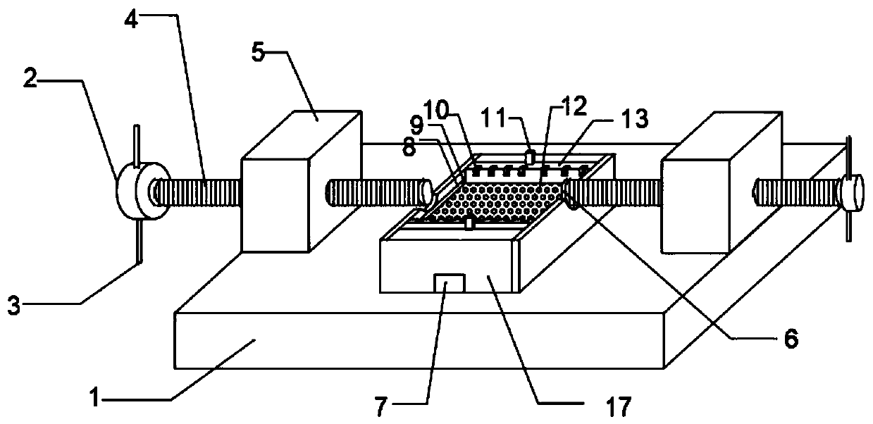
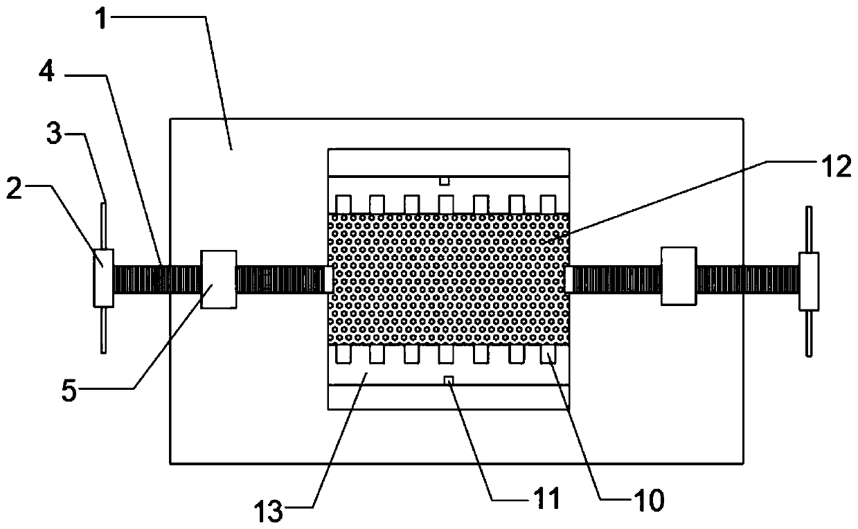
[0020] refer to Figure 1-2 , a network transformer welding fixture tooling, including a base 1, the outer walls of both ends of the top of the base 1 are fixedly connected with nuts 5, the inside of the nut 5 is provided with a screw 4, the screw 4 and the nut 5 are rotatably connected, and the screw 4 is away from the nut 5. One end is fixedly connected with a rotating block 2, the outer wall of the rotating block 2 is fixedly connected with a plurality of rotating rods 3, a workbench 17 is arranged between the two sides of the nut 5, the outer wall of the bottom of the workbench 17 is fixedly connected with the outer wall of the top of the base 1, and the workbench Both sides of the top of 17 are provided with a mobile platform 13, the top of the mobile platform 13 is provided with a plurality of card slots 10, the bottom of the mobile platform 13 is provided with a groove, and the inside of the groove is provided with a magnetic strip 7. 10 and the magnetic strip 7 triple ...

Embodiment 2

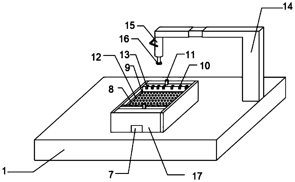
[0027] refer to image 3 , a network transformer welding fixture tooling, the outer wall of the top end of the base 1 is fixedly connected with a fixed frame 14, the fixed frame 14 is far away from the outer wall of the base 1, and the bottom outer wall is provided with a hand-pressed hydraulic rod 15, and the bottom of the hand-pressed hydraulic rod 15 is fixedly connected with a The second rubber pad 16.

[0028] When in use, just put the object between the mobile platforms 13, and then snap it into the card slot 10. After fixing the object, use the hand-pressed hydraulic rod 15 to press the object, and then put the magnetic strip 7 at the bottom of the workbench 17, and the whole is completely fixed. Afterwards just can carry out welding, by being provided with the fixing mechanism of hand pressure type hydraulic rod 15 fixing mechanism, draw-in groove 10 and magnetic strip 7 triple compound, can effectively improve fixing quality, thereby improve welding quality.


PUM


Abstract

The invention discloses a welding fixture for a network transformer. The welding fixture comprises a base; the outer walls of the two ends of the top part of the base are each fixedly connected with anut; a screw is arranged in each nut; each screw and the corresponding nut are rotatably connected; one end, far away from the corresponding nut, of each screw is fixedly connected with a rotating block; the outer wall of each rotating block is fixedly connected with a plurality of rotating rods; a worktable is arranged between the two opposite sides of the nuts; the outer wall of the bottom partof the worktable is fixedly connected the outer wall of the top part of the base; the two sides of the top part of the worktable are each provided with a moving table; a plurality of fixing slots areformed in the top part of each moving table; a groove is formed in the bottom part of each moving table; and a magnetic stripe is arranged in each groove. According to the welding fixture, by mainlyinstalling three types of main fixing mechanisms including bolt fixing mechanisms, the fixing slots and the magnetic stripes and setting the triple combined fixing mechanism of the bolt fixing mechanisms, the fixing slots and the magnetic stripes, the fixing quality can be effectively improved, and thereby, the welding quality is improved.

Description

technical field [0001] The invention relates to the technical field of fixtures, in particular to a network transformer welding fixtures. Background technique [0002] Network transformers are mainly used in various digital devices. Among them, network transformers using passive principles are composed of passive components such as inductors and capacitors, and are composed of the principle that the reactance of capacitors and inductive components changes with frequency. The advantage of this type of network transformer is that the circuit is relatively simple, does not require DC power supply, and has high reliability. [0003] In the production process of network transformers, welding will be involved, and fixtures and fixtures will be involved in the welding process. Today's fixtures and fixtures have a single clamping method and cannot be fixed in combination. It is easy to shift during the welding process, thus Lead to welding errors, so a fixture tool with composite t...

Claims


Application Information

Patent Timeline
Patent Type & Authority Applications(China)
IPC IPC(8): B23K37/04
CPCB23K37/0443
Inventor 陈小勇朱千林杨艳军
Owner LEIYANG YAXIANG ELECTRONICS TECH
Why Eureka
Try Eureka