Double guide-bar telescoping mechanism for motor vehicle equipment

A telescopic mechanism, double guide rod technology, applied in auxiliary devices, welding equipment, auxiliary welding equipment and other directions, can solve the problems of increased production cost, troublesome operation, damage of parts, etc., to avoid damage to parts, reduce floor space, Ease of use

Pending Publication Date: 2020-03-27
天津巴泰克汽车装备有限公司
View PDF0 Cites 0 Cited by
  • Summary
  • Abstract
  • Description
  • Claims
  • Application Information

AI Technical Summary

Problems solved by technology

[0003] The size of the existing guide rod telescopic mechanism is too large, it is inconvenient to weld the welding parts in a small space, and it is troublesome to operate. Since the guide rod telescopic mechanism does not have any limit structure or fixed structure, the guide rod pair is installed on the...

Method used


Image

  • Double guide-bar telescoping mechanism for motor vehicle equipment
  • Double guide-bar telescoping mechanism for motor vehicle equipment
  • Double guide-bar telescoping mechanism for motor vehicle equipment

Examples


Embodiment 1

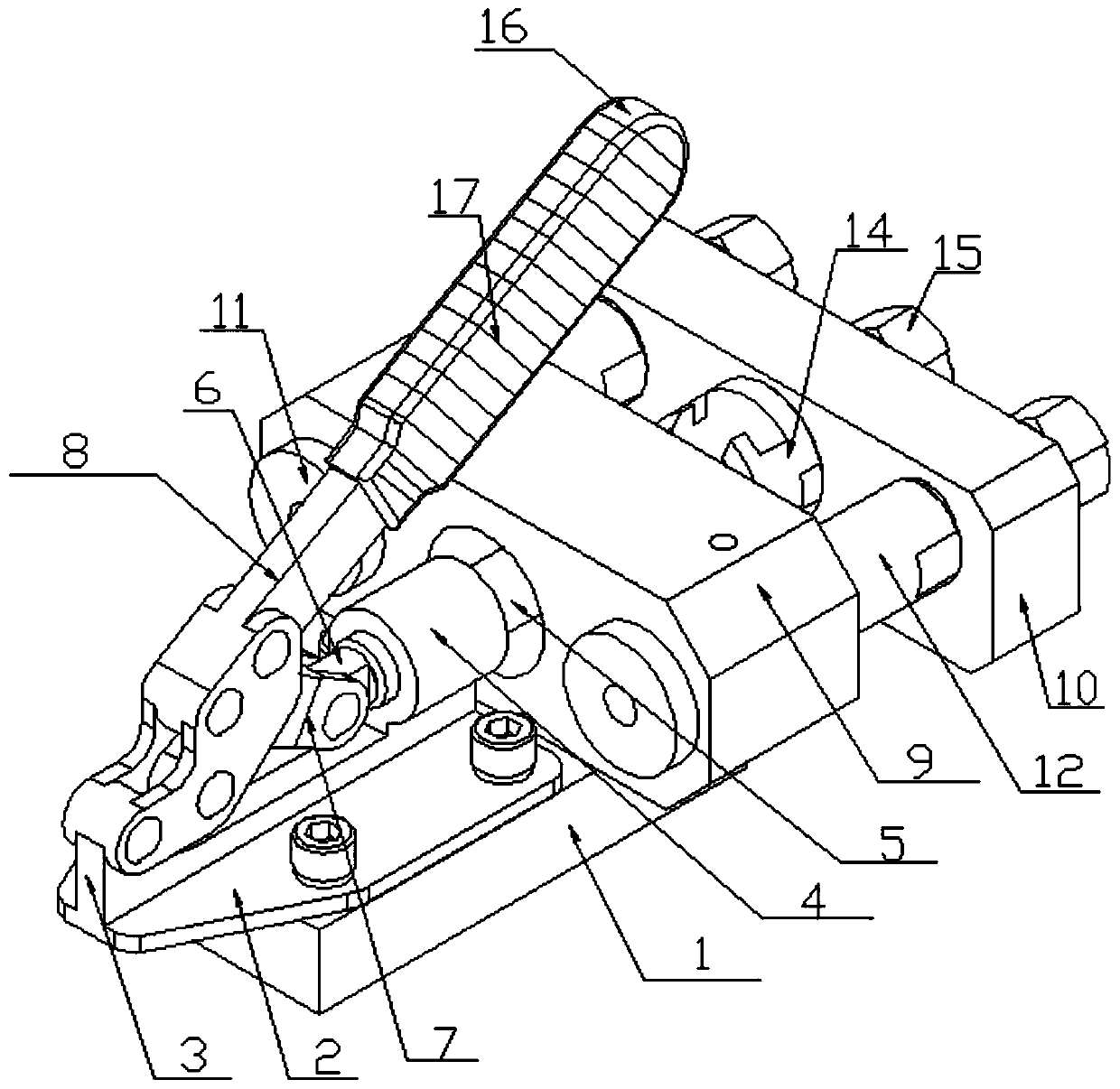
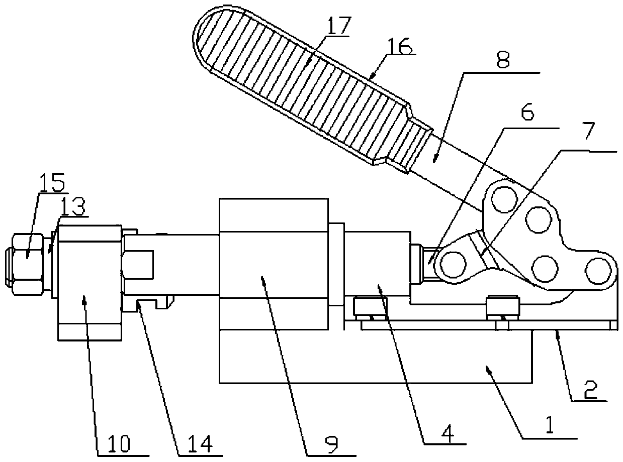
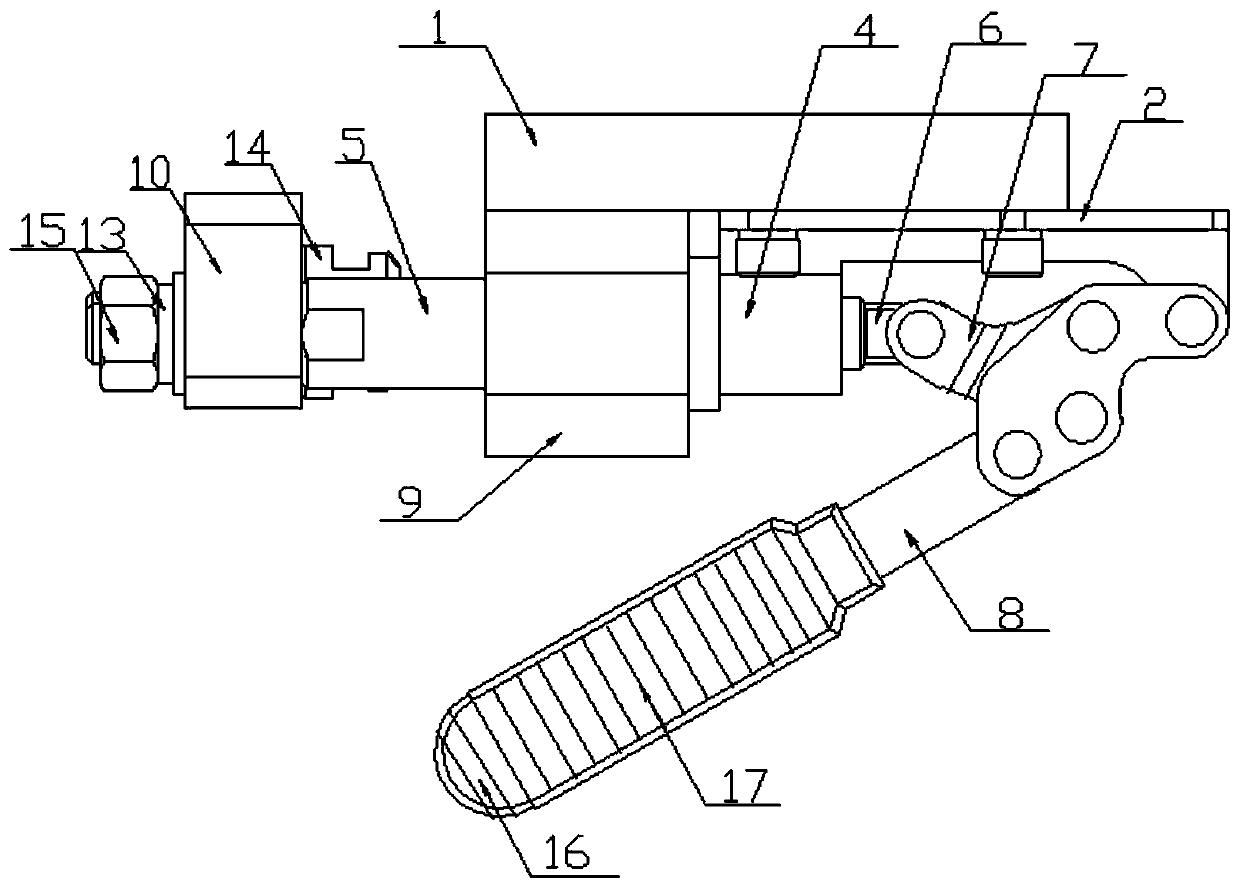
[0014] The invention provides a double guide rod telescopic mechanism for automobile equipment, which is characterized in that it includes a bottom plate 1, a mounting plate 2, a mounting block 3, a connecting column 4, a push rod 5, a connecting block 6, a pulling member 7, and a clamp 8 , piercing plate 9, vertical plate 10, perforation, mounting hole, stopper 11 in place, guide rod 12, mounting rod 13, movable joint 14, nut 15, the upper side of bottom plate 1 is installed with mounting plate 2 through bolts, and mounting plate 2 is "Inverted T-shaped" structure, one end of the mounting plate 2 is installed with a mounting block 3, the mounting block 3 and the mounting plate 2 are integrated, the mounting block 3 is equipped with a clamp 8, and the outer side of the clamp 8 is covered with a plastic shell 16, The plastic shell 16 is provided with anti-slip lines 17, the other end of the mounting plate 2 is welded with a connecting column 4, the connecting column 4 is connect...

Embodiment 2

[0016] The installation process of the present invention: first install the mounting plate 2 on the base plate 1, the through plate 9 is installed on the front side of the mounting plate 3, the through plate 9 is provided with two mounting holes and a perforation, and the pulling member 7 is installed on the On the mounting plate 2, the clamp 8 is installed on the mounting block 3 of the mounting plate 2, the clamp 8 is covered with a plastic shell 16, and the plastic shell 16 is provided with anti-slip lines 17, the clamp 8 is connected with the pulling block 7, and then Connect the connecting block 6 at one end of the push rod 5 with the puller 7, the inside of the push rod 5 is a hollow structure, the inside of the push rod 5 is provided with internal threads, the push rod 5 passes through the through hole of the through plate 9, and the vertical plate 10 Installed on the front side of the through-board 9, the vertical board 10 is provided with two installation holes and a t...


PUM


Abstract

The invention provides a double guide-bar telescoping mechanism for motor vehicle equipment, which is characterized by comprising a bottom plate, a mounting plate, a mounting block, a connecting post,a push rod, a connecting block, a pulling member, a clamp, a penetrating plate, a vertical plate, penetrating holes, mounting holes, in-place stop blocks, guide bars, a mounting rod, a movable jointand nuts, wherein the mounting plate is mounted on the upper side of the bottom plate by bolts; a mounting block is mounted at one end of the mounting plate; the clamp is mounted on the mounting block; non-slip lines are formed in a plastic shell; the other end of the mounting plate is welded with the connecting post; the connecting post is connected with the clamp through the pulling member; a through hole is formed in the connecting post; the connecting post is fixed with the connecting block through the through hole; the connecting block is connected with the pulling member; the push rod isinternally provided with internal threads; and the push rod is connected with a screw through the internal threads. According to the double guide-bar telescoping mechanism provided by the invention,the displacement of the guide bars are restricted, and at the same time, the movable joint and internal parts thereof are protected to avoid parts damage.

Description

technical field [0001] The invention relates to the technical field of telescopic mechanisms, in particular to a double-guide rod telescopic mechanism for automobile equipment. Background technique [0002] In the process of automobile production, some small parts need to be welded. Nowadays, in automobile welding equipment, auxiliary equipment is needed to fix the parts to facilitate welding. Today's auxiliary equipment is generally a guide rod telescopic mechanism. Today's guide rod The telescopic mechanism is a structure of three guide rods, and the fixed structure is installed on the guide rods. When fixing, the parts need to be placed in it. After the installation, the parts are controlled to move to the lower side of the welding gun. This application can be used well, but it can only Carry out simple fixation, after the welding is completed, move the parts to the outside, and the staff will take out the welded parts; [0003] The size of the existing guide rod telesco...

Claims


Application Information

Patent Timeline
IPC IPC(8): B23K37/00
CPCB23K37/00
Inventor 李薇
Owner 天津巴泰克汽车装备有限公司
Why Eureka
Try Eureka