Electric motor

An electric motor and electric conductor technology, applied in electric components, electromechanical devices, electrical components, etc., can solve the problems of increased particle load, cooling to ambient temperature, etc., to achieve the effects of improved cleanliness, simplified disassembly, and low overhead

Active Publication Date: 2020-03-24
ROBERT BOSCH GMBH
View PDF5 Cites 0 Cited by
  • Summary
  • Abstract
  • Description
  • Claims
  • Application Information

AI Technical Summary

Problems solved by technology

[0007] However, the arrangement as shown in FIG. 1 has some disadvantages: temperatures of up to approximately 200° C. can thus occur during operation of the electric motor 1 , while the electric motor 1 cools down to ambient temperature during the standstill phase
This means that the surface can only be realized with increased effort without resin and adhesive residues and / or with an increased particle load

Method used


Image

  • Electric motor
  • Electric motor
  • Electric motor

Examples


Embodiment Construction

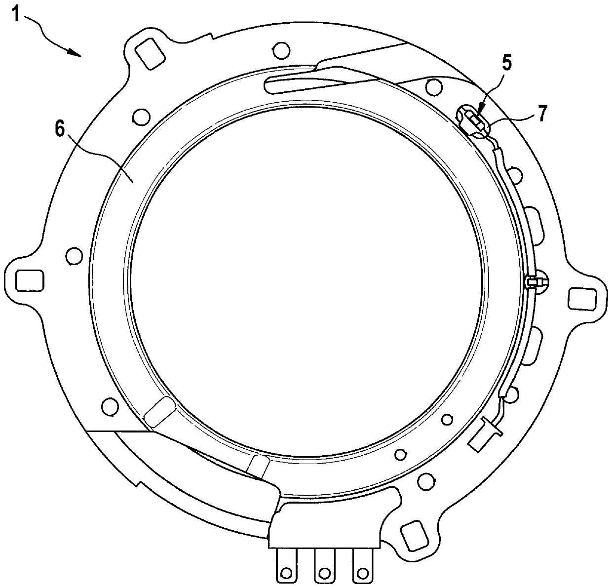
[0043] FIG. 1 schematically shows a detail of an electric motor 1 according to the prior art. The electric motor has already been described at the outset.

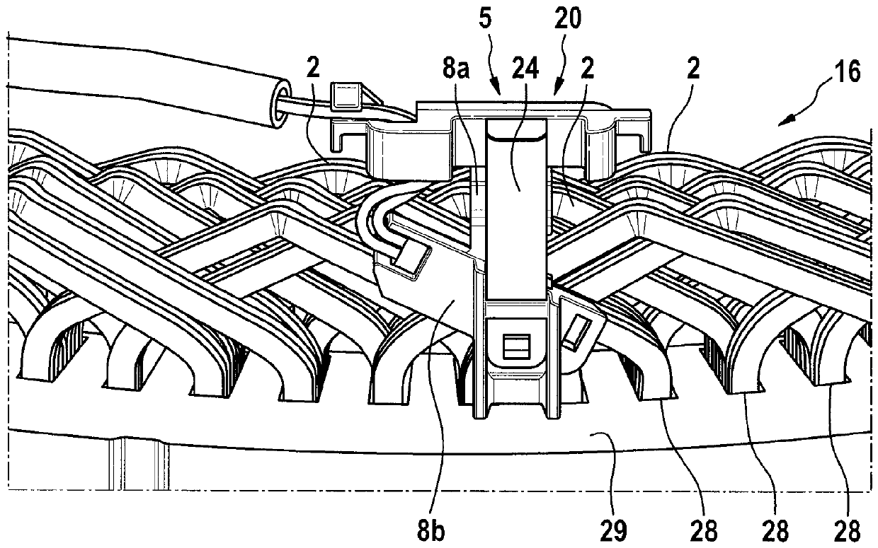
[0044] figure 2 A section of an electric motor 1 according to a first exemplary embodiment of the invention is shown schematically. The electric motor 1 includes a coil winding 16 with a plurality of conductors 2 for generating an electric field. Furthermore, the electric motor 1 includes a surrounding housing 6 .

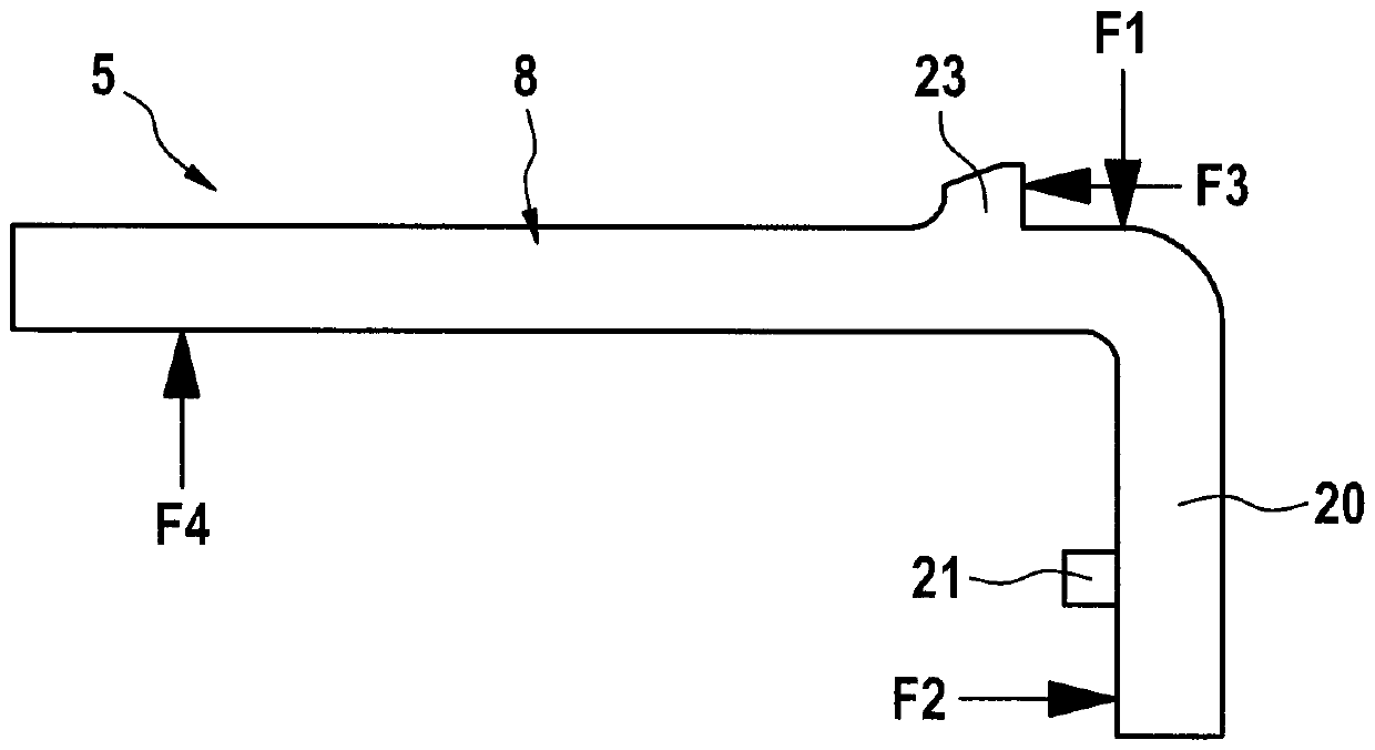
[0045] The temperature sensor 4 for detecting the temperature of the conductor 2 of the coil winding 16 is not connected, for example glued, to the conductor 2 of the coil winding 16 , as in the prior art, but via a support 5 clamping force is pressed onto the conductor 2 of the coil winding 16 . The coil winding 16 comprises a plurality of electrical conductors 2 wound around the sheet pack 3 so that the coil winding 16 is produced by winding the sheet pack 3 with the conductors 2 . The temperature sensor...


PUM


Abstract

The present invention relates to an electric motor (1) comprising a coil winding (16), and a temperature sensor (4), wherein the temperature sensor (4) is pressed onto an electrical conductor (2) of the coil winding (16) by means of a clamping force of a holding element (5), and wherein the holding element (5) is held between the temperature sensor (4) and a mating element (3, 6) due to said clamping force.

Description

technical field [0001] The invention relates to an electric motor. The invention relates in particular to the placement of temperature sensors on electric motors. Background technique [0002] It is known from the prior art to detect the temperature at the electric motor by means of a temperature sensor. Here, NTC (Negative Temperature Coefficient) is mostly used. The temperature information can be transmitted to the controller of the electric motor, which uses this information for the purpose of steering the electric motor. [0003] Temperature sensors are usually placed on the coil windings of electric motors. The coil winding comprises a plurality of electrical conductors which are wound around the sheet pack, wherein the temperature sensor is preferably arranged on one of the electrical conductors. A sheet pack is here a stack of a plurality of sheet metal elements, wherein the stack represents the stator base body and / or the rotor base body. An electrical conductor...

Claims


Application Information

Patent Timeline
Patent Type & Authority Applications(China)
IPC IPC(8): H02K11/25G01K1/14
CPCG01K1/143H02K11/25
Inventor R.马利D.贝格曼O.贝克费尔德P.马沙尔D.格拉泽
Owner ROBERT BOSCH GMBH
Why Eureka
Try Eureka