Carton cover hinge closing equipment
A technology of closing equipment and cover pages, applied in the direction of unsealing of vacuum seals, can solve problems such as re-lifting and affecting work efficiency, and achieve the effect of guaranteeing and improving efficiency.
- Summary
- Abstract
- Description
- Claims
- Application Information
AI Technical Summary
Problems solved by technology
Method used
Image

Examples
no. 1 example
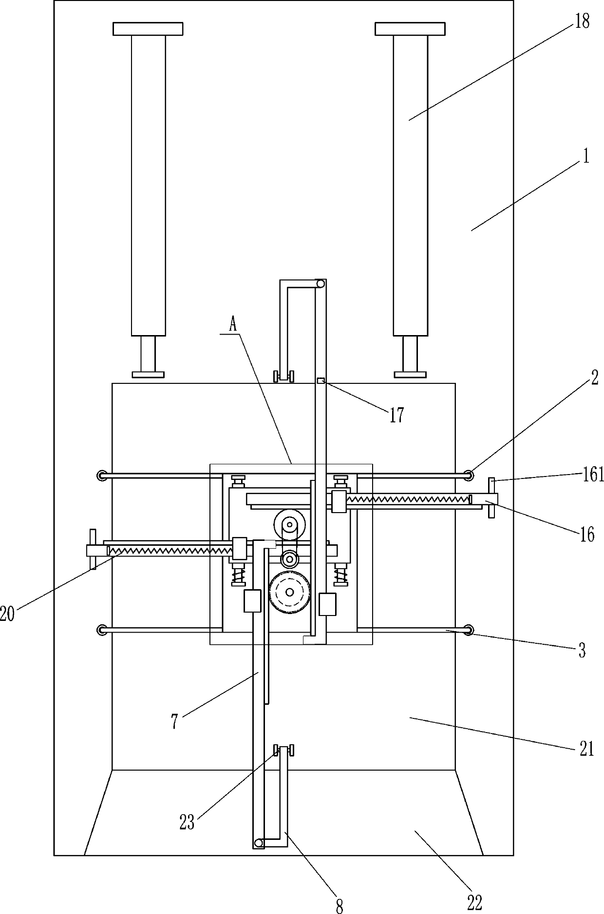
[0017] see Figure 1-3 , a carton cover page closing device, including a base 1, a first cylinder 2, a connecting rod 3 and a base plate 4, two first cylinders 2 are symmetrically arranged on the left and right sides of the front side of the top of the base 1, and the first cylinder 2 It is connected to the base 1 by means of bolt connection, the connecting rod 3 is connected to the telescopic rod of the first cylinder 2, and the bottom plate 4 is connected between the connecting rods 3 on the left and right sides, and the bottom plate 4 is connected to the connecting rod 3 by welding. connected, also includes electric gear 5, first guide seat 6, toothed puller bar 7 and L-shaped bar 8, electric gear 5 is installed on the front side of bottom plate 4 top, left and right sides of bottom plate 4 top are symmetrically provided with first Guide seat 6, the first guide seat 6 is connected with the base plate 4 by means of bolt connection, the first guide seat 6 is located on the le...
no. 2 example
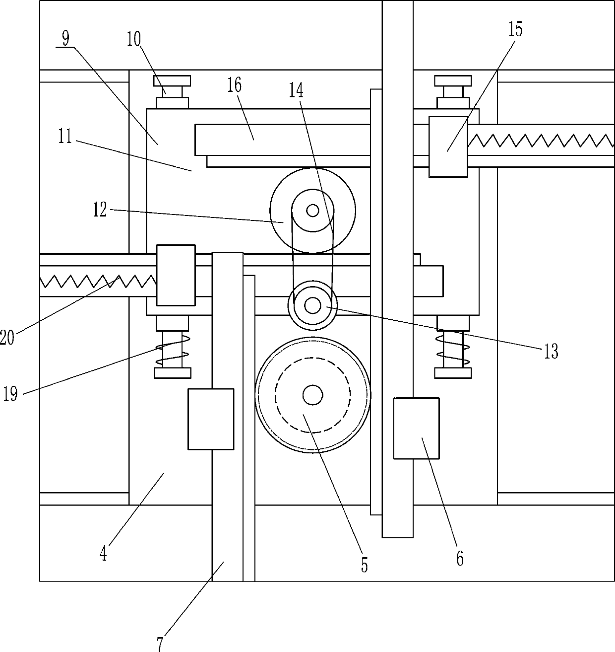
[0020] see Figure 1-2 , also includes a transmission mechanism 9, the transmission mechanism 9 includes a slide rail 10, a mounting plate 11, a large belt gear 12, a small belt gear 13, a flat belt 14, a second guide seat 15, a rack 16, a puller 161, a card block 17 and the second cylinder 18, the left and right sides of the upper rear part of the bottom plate 4 are symmetrically provided with slide rails 10, and the two slide rails 10 are respectively located on the left and right sides of the electric gear 5, and the slide rails 10 on the left and right sides are slidingly provided with Mounting plate 11, mounting plate 11 is positioned at band tooth puller bar 7 below, and mounting plate 11 top middle rotation type is provided with large belt gear 12, and mounting plate 11 top front side middle rotation type is provided with small belt gear 13, and small belt gear 13 is positioned at On the rear side of the electric gear 5, a flat belt 14 is wound between the large belt ge...
no. 3 example
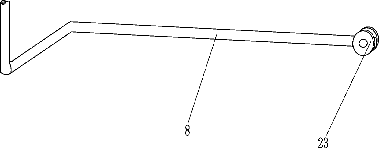
[0023] see Figure 1-3 , also includes a first spring 19, a second spring 20 and an auxiliary wheel 23, the front sides of the slide rails 10 on the left and right sides are all sleeved with the first spring 19, and the ends of the first spring 19 are connected with the mounting plate 11 and the slide rail respectively. 10, the second guide seats 15 on the left and right sides are connected with the second spring 20, the ends of the second springs 20 on the left and right sides are respectively connected with the rear ends of the racks 16 on the left and right sides, and the base of the second cylinder 18 front side 1 is provided with a placement groove 21, the shape of the placement groove 21 is rectangular, and the base 1 on the front side of the placement groove 21 is provided with a chute 22, the chute 22 communicates with the placement groove 21, and the tails of the L-shaped rods 8 on the front and rear sides are all connected. There is auxiliary wheel 23, and auxiliary ...
PUM
 Abstract
Description
Claims
Application Information
 - R&D
- Intellectual Property
- Life Sciences
- Materials
- Tech Scout
- Unparalleled Data Quality
- Higher Quality Content
- 60% Fewer Hallucinations
Browse by: Latest US Patents, China's latest patents, Technical Efficacy Thesaurus, Application Domain, Technology Topic, Popular Technical Reports.
© 2025 PatSnap. All rights reserved.Legal|Privacy policy|Modern Slavery Act Transparency Statement|Sitemap|About US| Contact US: help@patsnap.com