
Precast slab cutting device for construction site

A cutting device and prefabricated panel technology, applied in the direction of work accessories, manufacturing tools, stone processing tools, etc., can solve the problems of inconvenience, cumbersome operation process, and large volume of prefabricated panels, and achieve the effect of small volume, compact structure and easy installation

Active Publication Date: 2020-03-24
颍上晶宫绿建节能建筑有限责任公司
View PDF6 Cites 0 Cited by
  • Summary
  • Abstract
  • Description
  • Claims
  • Application Information

AI Technical Summary

Problems solved by technology

[0002] Prefabricated panels are concrete prefabricated parts produced and processed on the prefabrication site, which are directly transported to the construction site for installation. After a large number of prefabricated panels are delivered to the construction site, they are directly assembled. The current construction method has changed from traditional pouring to prefabricated buildings. , and prefabricated parts are an indispensable part of it. However, in the actual construction process, due to the large volume of prefabricated panels, when cutting is required, large-scale cutting equipment needs to be installed on the construction site, and the prefabricated panels are lifted to the cutting site by crane. station, and then use the cutting equipment to precisely cut the prefabricated panels, so that the prefabricated panels meet the assembly requirements. The operation process is cumbersome and requires the cooperation of multiple people, which is very inconvenient

Method used


Image

  • Precast slab cutting device for construction site
  • Precast slab cutting device for construction site
  • Precast slab cutting device for construction site

Examples


Embodiment Construction

[0018] In order to make the object, technical solution and advantages of the present invention clearer, the present invention will be described in further detail below in conjunction with specific embodiments and with reference to the accompanying drawings.

[0019] It should be noted that all expressions using "first" and "second" in the embodiments of the present invention are to distinguish two entities with the same name but different parameters or parameters that are not the same, see "first" and "second" It is only for the convenience of expression, and should not be understood as limiting the embodiments of the present invention. In addition, the terms of direction and position mentioned in the present invention, such as "upper", "middle", "lower", "front", "rear", "Left", "right", "inner", "outer", "side", etc., are only referring to the directions and positions of the attached drawings. Therefore, the terms of directions and positions used are for explaining and unders...


PUM


Abstract

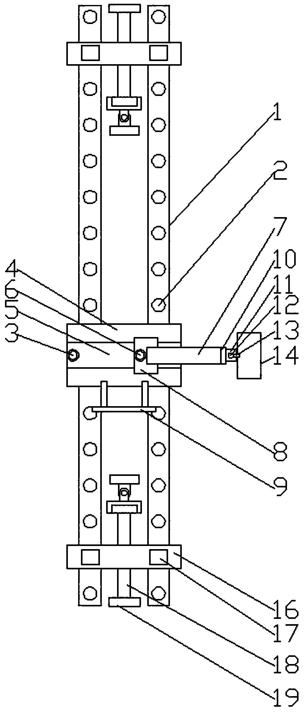
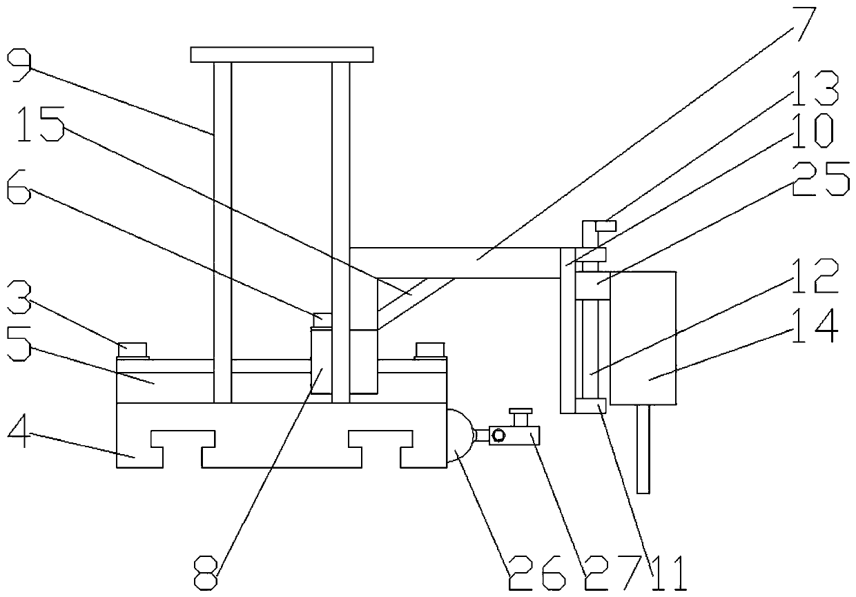
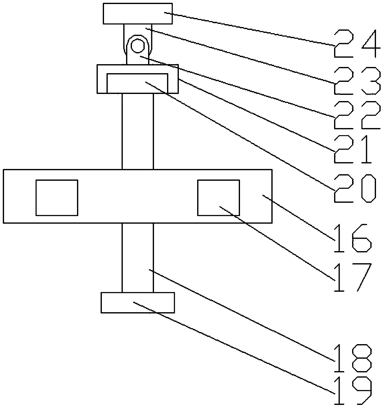
The invention discloses a precast slab cutting device for a construction site. The device comprises two first sliding rails which are arranged in parallel. The two ends of the two first sliding railsare jointly sleeved with a sliding plate. A plurality of through holes are equidistantly formed in the surface of each first sliding rail in the length direction; a locking pin penetrates through theupper end of the sliding plate; the lower end of the locking pin is inserted into the through hole; a screw rod II in threaded connection is arranged on the sliding plate; the two first sliding railsare further provided with sliding bases connected in a sliding mode; second sliding rails are arranged at the upper ends of the sliding bases; sliding blocks in sliding connection are arranged on thesecond sliding rails; a locking bolt in threaded connection is vertically arranged at the upper end of the sliding block; and the bottom of the locking bolt abuts against the upper end face of each second sliding rail. The precast slab cutting device for the construction site is compact in structure, small in size, easy to install, capable of being installed and used by a single worker, simple andefficient in adjusting method and suitable for cutting operation of precast slabs with the large size.

Description

technical field [0001] The invention relates to the field of prefabricated panel cutting devices, in particular to a prefabricated panel cutting device for construction sites. Background technique [0002] Prefabricated panels are concrete prefabricated parts produced and processed on the prefabrication site, which are directly transported to the construction site for installation. After a large number of prefabricated panels are delivered to the construction site, they are directly assembled. The current construction method has changed from traditional pouring to prefabricated buildings. , and prefabricated parts are an indispensable part of it. However, in the actual construction process, due to the large volume of prefabricated panels, when cutting is required, large-scale cutting equipment needs to be installed on the construction site, and the prefabricated panels are lifted to the cutting site by crane. Station, and then use the cutting equipment to precisely cut the p...

Claims


Application Information

Patent Timeline
Patent Type & Authority Applications(China)
IPC IPC(8): B28D1/22B28D7/02
CPCB28D1/22B28D7/02
Inventor 王晗
Owner 颍上晶宫绿建节能建筑有限责任公司
Learn More