
Filtering device and filtering system

A filter device and filter element technology, applied in chemical instruments and methods, water/sludge/sewage treatment, reverse osmosis, etc., can solve problems such as high TDS value, reduce excessive TDS value, reduce manufacturing cost, and reduce structural complexity degree of effect

Pending Publication Date: 2020-03-24
JOMOO KITCHEN & BATHROOM
View PDF0 Cites 1 Cited by
  • Summary
  • Abstract
  • Description
  • Claims
  • Application Information

AI Technical Summary

Problems solved by technology

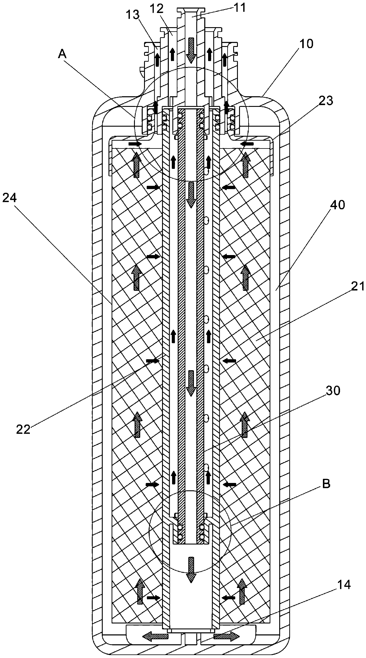
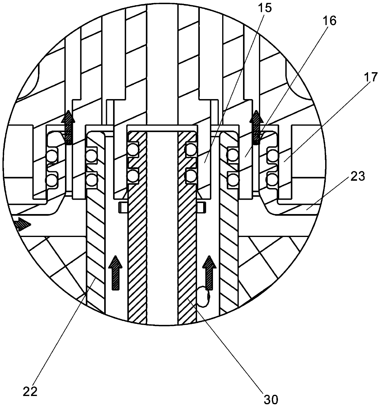
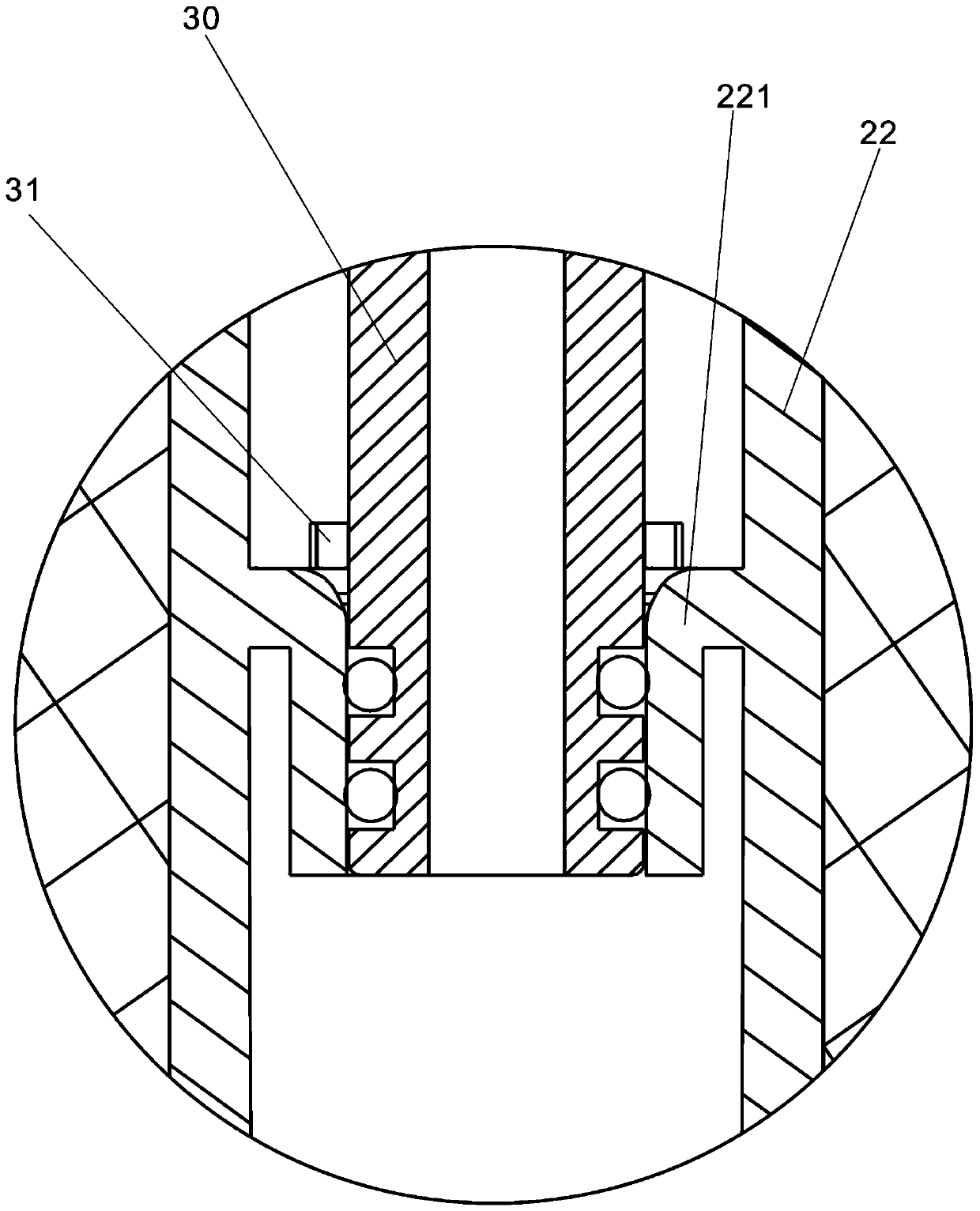
[0004] The purpose of the present invention is to overcome the above-mentioned defects or problems in the background technology, and provide a filter device and a filter system, which can reduce the TDS value of the pure water side after shutdown, and solve the problem that the TDS value of the first glass of water in the reverse osmosis water purification device is too high. high problem

Method used


Image

  • Filtering device and filtering system
  • Filtering device and filtering system
  • Filtering device and filtering system

Examples


Embodiment 2

[0060] The present invention also provides Embodiment 2, which is different from Embodiment 1 in that the structure of the water storage component is different. In Embodiment 2, the water storage component is an air bag water tank 41 arranged outside the casing 10 and communicated with the raw water inlet 11 , specifically, such as Figure 6 As shown, the air bag water tank 41 includes a water tank shell, and a cavity is formed inside the shell, and the cavity has an opening, and the opening is directly connected to the raw water inlet 11 on the shell 10, so that the raw water can reach the raw water inlet 11 At the same time, it can enter the cavity in the water tank shell at the same time. At the same time, an elastic film is arranged in the cavity, and the elastic film divides the cavity into a closed air cavity and a connection with the raw water inlet 11. Raw water enters the water storage chamber, and because there is a large pressure at the raw water end when the filter...

Embodiment 3

[0061] The present invention also provides Embodiment 3, which differs from Embodiment 2 in that the water storage component further includes a water storage cavity 42 , and the airbag water tank 41 communicates with the water storage cavity 42 . Specifically, such as Figure 7 As shown, the structure of the air bag water tank 41 is the same as that of Embodiment 2, and the structure of the water storage chamber 42 is the same as that of the raw water chamber 40 in Embodiment 1, but the water storage chamber 42 is a vacuum. The opening of the airbag water tank 41 is set to communicate with the top of the water storage chamber 42. When the filter device is running, the raw water enters the water storage chamber 42 after passing through the water inlet pipe 30, and then enters the water storage chamber of the airbag water tank 41 to compress the air. The volume of the cavity shrinks; when the filter device stops running, the pressure becomes unbalanced, and the air cavity recove...


PUM


Abstract

The invention discloses a filtering device and a filtering system. The filtering device comprises a shell, a filter element, a raw water passing path, a pure water passing path and a concentrated water passing path, wherein the raw water passing path comprises a raw water inlet formed in the shell; the pure water passing path comprises a central pipe arranged in the filter element and a pure wateroutlet formed in the shell; the concentrated water passing path comprises a concentrated water outlet formed in the shell; the bottom end of the filter element is communicated with the raw water passing path to allow raw water to enter; and the top end of the filter element is communicated with the concentrated water passing path to allow concentrated water to be discharged. In addition, the filtering device further comprises a water storage part, wherein the water storage part is communicated with the raw water passing path, and is used for storing raw water when the filtering device is in operation and pushing the stored raw water to enter the filter element from the bottom end of the filter element by utilizing air pressure when the filtering device is shut down so as to wash the filter element. According to the filtering device and the filtering system adopting such a structure, backflushing of the filter element is realized through water stored in the water storage part, so the TDS value of the first cup of water can be effectively reduced and the service life of the filter element is prolonged.

Description

technical field [0001] The invention relates to the technical field of filter elements, in particular to a filter device and a filter system. Background technique [0002] The main component of the reverse osmosis water purification device is the reverse osmosis membrane filter, which generally has three water inlets and outlets: water inlet, pure water outlet and concentrated water outlet, and its structure generally includes core material, filter shell and central tube, core The material is wound around the central tube, and the filter core shell is set on the outer wall of the core material, so that the raw water can only enter from one end of the filter core, and the concentrated water can only flow out from the other end of the filter core. Receive pure water. By pressurizing the side of the water inlet, the municipal tap water enters the filter element through the water inlet, and then the tap water is filtered through the reverse osmosis membrane, and the filtered pu...

Claims


Application Information

Patent Timeline
Patent Type & Authority Applications(China)
IPC IPC(8): B01D61/08B01D65/02C02F1/44
CPCB01D61/025B01D61/027B01D61/08B01D65/02C02F1/441C02F1/442B01D2313/04B01D2313/18B01D2313/243B01D2321/10B01D2321/12
Inventor 林孝发林孝山谢添明汪仁虎王运灿
Owner JOMOO KITCHEN & BATHROOM
Learn More