Cavity cleaning structure and oven

A cavity and oven technology, which is applied in cleaning equipment, household cleaning devices, roasters/barbecue grids, etc., can solve the problems of bacteria, grease or stains that are not cleaned up, and endanger consumers' health, so as to improve the user experience. Effect

Pending Publication Date: 2020-03-24
SHANGHAI CHUNMI ELECTRONICS TECH CO LTD
View PDF0 Cites 0 Cited by
  • Summary
  • Abstract
  • Description
  • Claims
  • Application Information

AI Technical Summary

Problems solved by technology

[0002] During the process of cooking food with a box-type cooking appliance such as an oven, the food will be heated. However, during the heating process, the food will have dirt such as grease or water stains attached to the inner wall of the oven cavity. The back part is relatively deep, and it is difficult for consumers to clean. If the residual grease or stains are not cleaned, bacteria will breed and endanger the health of consumers.

Method used


Image

  • Cavity cleaning structure and oven
  • Cavity cleaning structure and oven
  • Cavity cleaning structure and oven

Examples


Embodiment Construction

[0052] The exemplary embodiments will be described in detail here, and examples thereof are shown in the accompanying drawings. When the following description refers to the accompanying drawings, unless otherwise indicated, the same numbers in different drawings represent the same or similar elements. The implementation manners described in the following exemplary embodiments do not represent all implementation manners consistent with the present disclosure. Rather, they are only examples of devices and methods consistent with some aspects of the present disclosure as detailed in the appended claims.

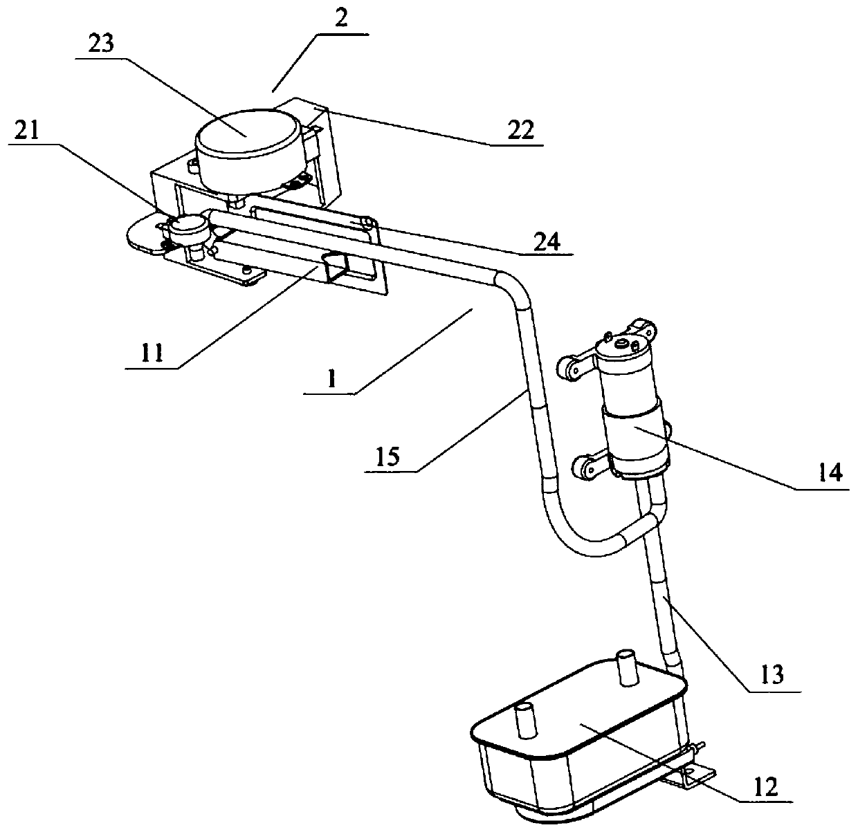
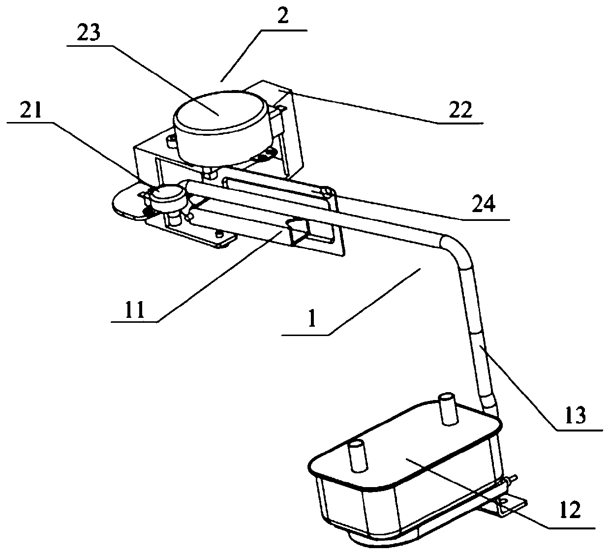
[0053] figure 1 It is a schematic structural diagram of a cavity cleaning structure according to an exemplary embodiment, such as figure 1 As shown, the cleaning structure includes:

[0054] Cleaning fluid output device 11 and rotating mechanism 22;

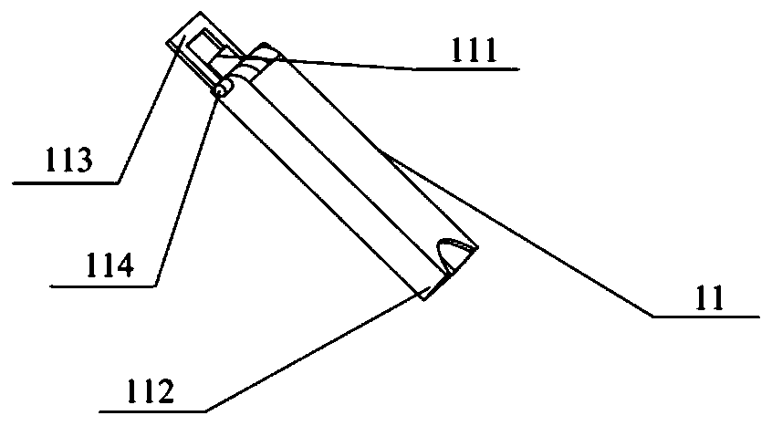
[0055] The rotating mechanism 2 and the liquid output port 11 of the cleaning liquid output device 1 are both located at the opening o...


PUM


Abstract

The invention relates to a cavity cleaning structure and an oven. The cavity cleaning structure comprises a cleaning liquid output device and a rotating mechanism. The rotating mechanism and a liquidoutput port of the cleaning liquid output device are both located at an opening of the cavity. The rotating mechanism is connected with the liquid output port and used for controlling the liquid output port to rotate so that the liquid output port can turn to different positions in the cavity. The liquid output port can be turned to different positions in the cavity by the rotating mechanism. Therefore, the liquid output by the liquid output port can be in contact with different positions in the cavity; and the liquid output by the liquid output port cleans different positions in the cavity, especially the top or the rear part of the cavity which is not easy to clean by a user, so that the problems that residual dirt breeds bacteria and the like due to the fact that the consumer cannot clean the cavity are avoided, and the use experience of the consumer is improved.

Description

Technical field [0001] The present disclosure relates to the technical field of cooking appliances, in particular to a cavity cleaning structure and an oven. Background technique [0002] In the process of cooking food with a box-type cooking appliance such as an oven, the food will be heated. However, the food will have grease or water stains and other dirt attached to the inner wall of the oven cavity during the heating process. The rear part is relatively deep, and it is difficult for consumers to clean it. If the residual grease or stains are not cleaned, bacteria will breed and harm consumers' health. Summary of the invention [0003] In order to overcome the problems in the related art, embodiments of the present disclosure provide a cavity cleaning structure and an oven. [0004] The technical solution is as follows: [0005] According to a first aspect of the embodiments of the present disclosure, there is provided a cavity cleaning structure, including: [0006] Cleaning flu...

Claims


Application Information

Patent Timeline
Patent Type & Authority Applications(China)
IPC IPC(8): A47L15/00A47L15/42A47J37/06
CPCA47J37/0664A47L15/0092A47L15/42A47L15/4217
Inventor 杨华刘锦森梁峰刘福波杨有如郑秀谦戴建亮龚圆杰陈春恒贾贵胜周铭伦
Owner SHANGHAI CHUNMI ELECTRONICS TECH CO LTD
Why Eureka
Try Eureka