Malfunction detection device for passenger conveyor

A technology for passenger conveyors, anomaly detection, used in transportation and packaging, escalators, etc., to solve problems such as injuries

Active Publication Date: 2020-03-17
MITSUBISHI ELECTRIC CORP
View PDF7 Cites 3 Cited by
  • Summary
  • Abstract
  • Description
  • Claims
  • Application Information

AI Technical Summary

Problems solved by technology

As a result, the sides of each step come into contact with the skirt, thereby injuring

Method used


Image

  • Malfunction detection device for passenger conveyor
  • Malfunction detection device for passenger conveyor
  • Malfunction detection device for passenger conveyor

Examples


Embodiment approach 1

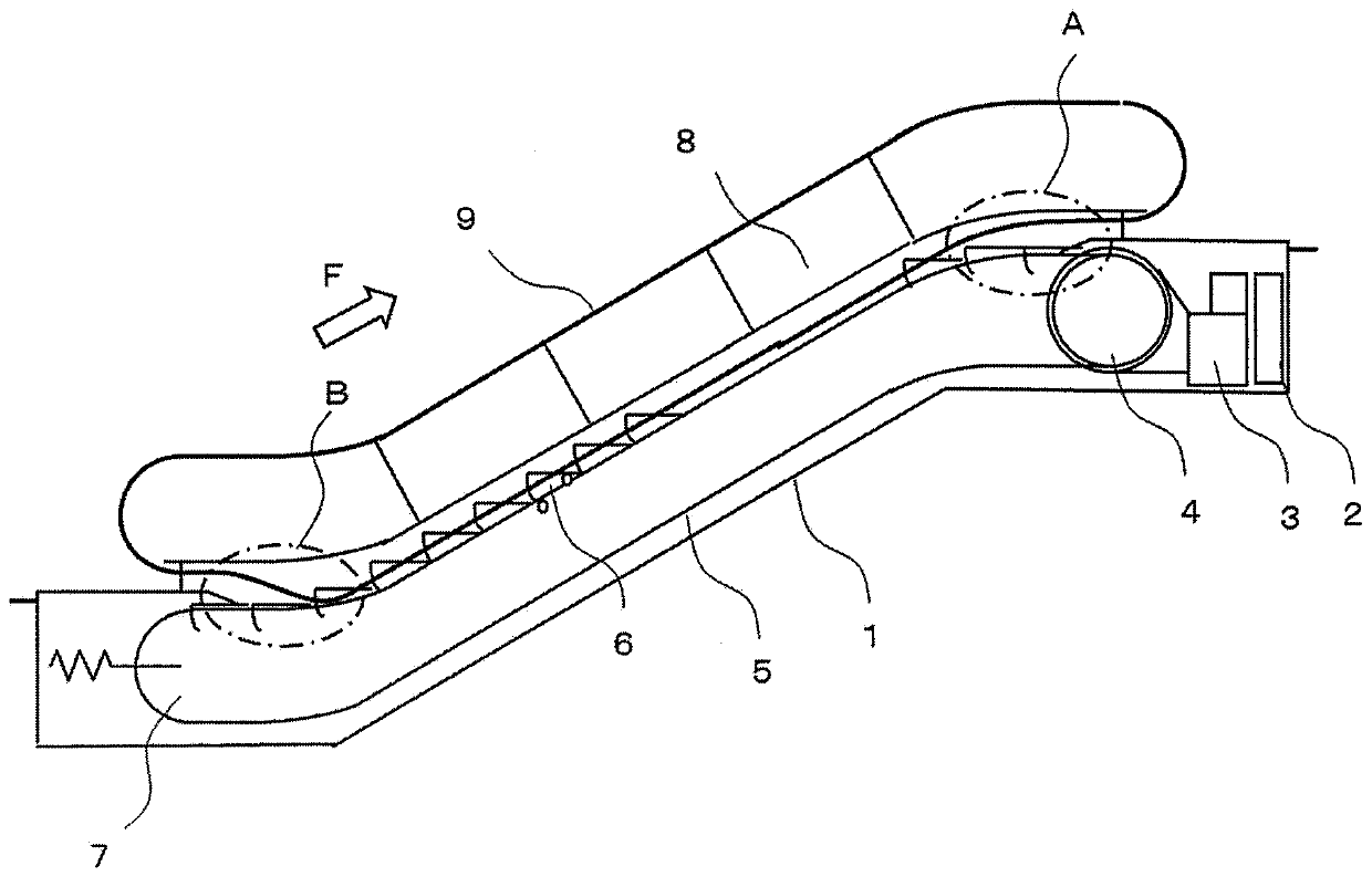
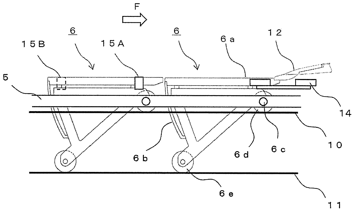
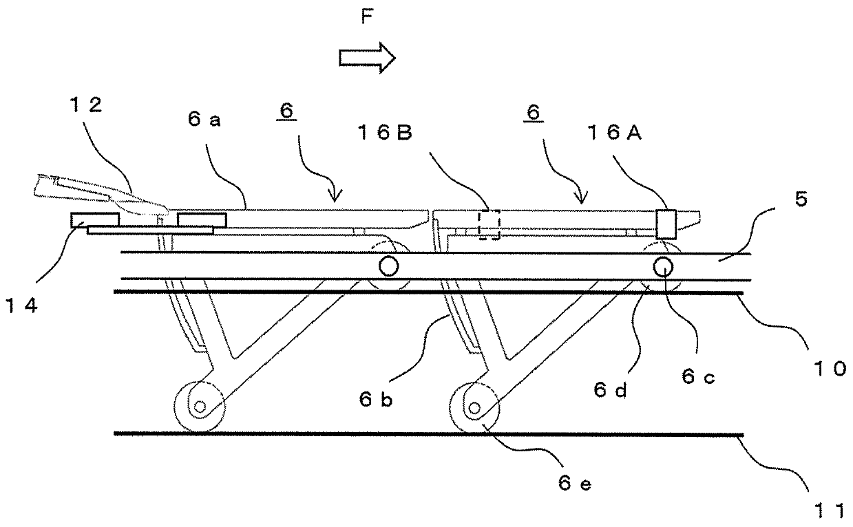
[0028] figure 1 It is a schematic diagram showing the passenger conveyor in which the abnormality detection device in Embodiment 1 of this invention is arrange|positioned. figure 2 is showing figure 1 A partial enlarged view of the horizontal portion A of the upper side, image 3 is showing figure 1 A partial enlarged view of the horizontal section B on the lower side of . also, Figure 4 is to be observed from above figure 2 The diagram of is arranged so that the direction of travel of the steps faces up and down.

[0029] like figure 1 As shown, the passenger conveyor has a truss 1, a control panel 2, a driving machine 3, a step sprocket 4 arranged on the upper reversing part, a step chain 5 wound on the step sprocket 4, a plurality of steps 6, and a lower reversing 7, a plurality of railings 8, and a moving handrail 9. The step sprocket 4 is rotated by the driving machine 3 whose operation is controlled by the control panel 2 . in addition, figure 1 One side of ...


PUM


Abstract

This malfunction detection device for a passenger conveyor includes: a first sensor disposed on an upper-side horizontal part; a second sensor disposed on a lower-side horizontal part; and a control device into which the output from the first sensor and the second sensor is input. The first sensor and the second sensor each measure the distance to the side surface, along the advancement direction,of each of multiple steps. On the basis of the amount of change in the values measured by the first sensor and the second sensor, the control device detects malfunctions in the passenger conveyor.

Description

technical field [0001] The present invention relates to a device for detecting an abnormality of a drive system of a step based on the attitude of the step of a passenger conveyor. Background technique [0002] Conventionally, a gap is set between each step of the passenger conveyor and the apron so that the steps do not touch during travel. Each step travels along the traveling direction of each step through the step chains arranged on both sides of each step. Each step chain may be stretched due to changes over time or external factors. When stretching of each step chain is not uniform, each step may run obliquely with respect to the traveling direction. Then, the sides of each step come into contact with the apron and are injured. [0003] Therefore, a technique has been disclosed in which a distance sensor for measuring the distance to the side of the step is placed at a position where the step moves horizontally and the attitude of the step is not corrected, and the ...

Claims


Application Information

Patent Timeline
Patent Type & Authority Applications(China)
IPC IPC(8): B66B29/00B66B27/00
CPCB66B25/006B66B23/12B66B27/00B66B29/00
Inventor 小仓健司
Owner MITSUBISHI ELECTRIC CORP
Why Eureka
Try Eureka