Eureka AIR delivers breakthrough ideas for toughest innovation challenges, trusted by R&D personnel around the world.

Monitoring system

A monitoring system and micro-control technology, applied in color TV parts, electrical components, image reproducers using projection devices, etc., can solve problems such as extremely space-consuming, time-consuming, inability to continue monitoring, and inability to achieve real-time replacement. , to achieve the effect of reducing construction costs

Pending Publication Date: 2020-03-17
上海仪电电子多媒体有限公司
View PDF0 Cites 0 Cited by
  • Summary
  • Abstract
  • Description
  • Claims
  • Application Information

AI Technical Summary

Problems solved by technology

[0003] However, the disadvantage of the video wall display system is that if one of the display screens of the video wall display system fails, the location monitored by the screen will lose the image
Furthermore, since the display screen is not only expensive but takes up a lot of space, it also takes time to install, so the effect of real-time replacement cannot be achieved
In other words, when one of the display screens fails, it will inevitably take some time to continue monitoring during the process of replacing the new screen.

Method used


Image

  • Monitoring system

Examples


Embodiment Construction

[0021] The implementation of the present invention is described below through specific specific examples, and those skilled in the art can easily understand other advantages and effects of the present invention from the content disclosed in this specification.

[0022] It should be noted that the structures, proportions, sizes, etc. shown in the drawings attached to this specification are only used to match the content disclosed in the specification, for those who are familiar with this technology to understand and read, and are not used to limit the implementation of the present invention. Restricted conditions, any modification of structure, change of proportional relationship or adjustment of size shall fall within the scope covered by the technical content disclosed in the present invention without affecting the effect and purpose of the present invention. Inside. At the same time, terms such as "upper", "lower", "inner" and "one" quoted in this specification are only for ...


PUM


Abstract

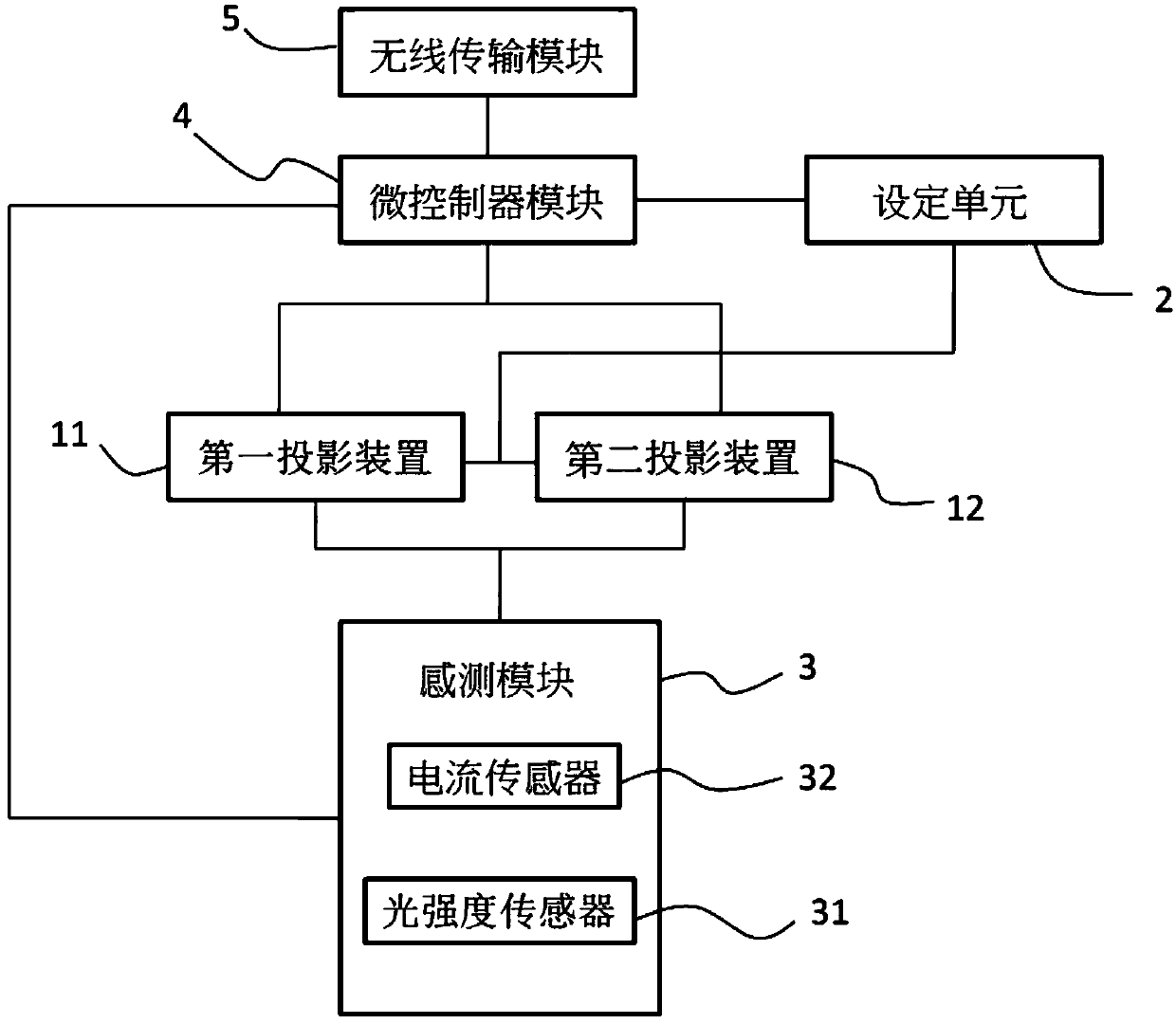
A monitoring system is installed on two projection devices and comprises a setting unit, a sensing module and a microcontroller module. The setting unit sets the two projection devices as a first projection device and a second projection device. When one of the first projection device and the second projection device is in an operating state, the other is in a closed state. The sensing module is arranged on the first projection device and the second projection device. The sensing module is used for sensing the operation state of the first projection device or the second projection device and outputting a sensing signal. The microcontroller module detects the operation state of the first projection device according to the sensing signal, and outputs a control signal to the second projectiondevice when the first projection device breaks down; or detects the operation state of the second projection device according to the sensing signal, and outputs a control signal to the first projection device when the second projection device fails.

Description

technical field [0001] The present invention relates to a monitoring system, and more specifically relates to a real-time monitoring system capable of not being affected by equipment failures. Background technique [0002] When using surveillance systems to monitor large areas over long periods of time, the reliability of the equipment is very important. Generally, multiple LCD or LED screens are spliced ​​into a large-area splicing screen display system. [0003] However, the disadvantage of the splicing screen display system is that if one of the display screens of the splicing screen display system fails, the position monitored by the screen will lose the image. Furthermore, since the display screen is not only expensive but also takes up a lot of space, it also takes time to install, so the effect of real-time replacement cannot be achieved. In other words, when one of the display screens breaks down, it will inevitably take some time to continue monitoring during the ...

Claims


Application Information

Patent Timeline
IPC IPC(8): H04N9/31
CPCH04N9/3141H04N9/3194
Inventor 李锋
Owner 上海仪电电子多媒体有限公司
Why Eureka
Eureka Blog
Learn More