Deceleration strip with warning function

A technology of speed bumps and functions, applied in the field of transportation, can solve the problems of speed bumps, speed reduction, etc., and achieve the effect of convenient use and driving safety

Active Publication Date: 2020-03-17
合肥慧问机械设计有限公司
View PDF9 Cites 7 Cited by
  • Summary
  • Abstract
  • Description
  • Claims
  • Application Information

AI Technical Summary

Problems solved by technology

[0005] The purpose of the present invention is to solve the problem that most traditional deceleration belts are difficult to reduce the speed of the vehicle, and to provide a deceleration belt with a warning function that can effectively reduce the speed of the vehicle

Method used


Image

  • Deceleration strip with warning function
  • Deceleration strip with warning function
  • Deceleration strip with warning function

Examples


Embodiment 1

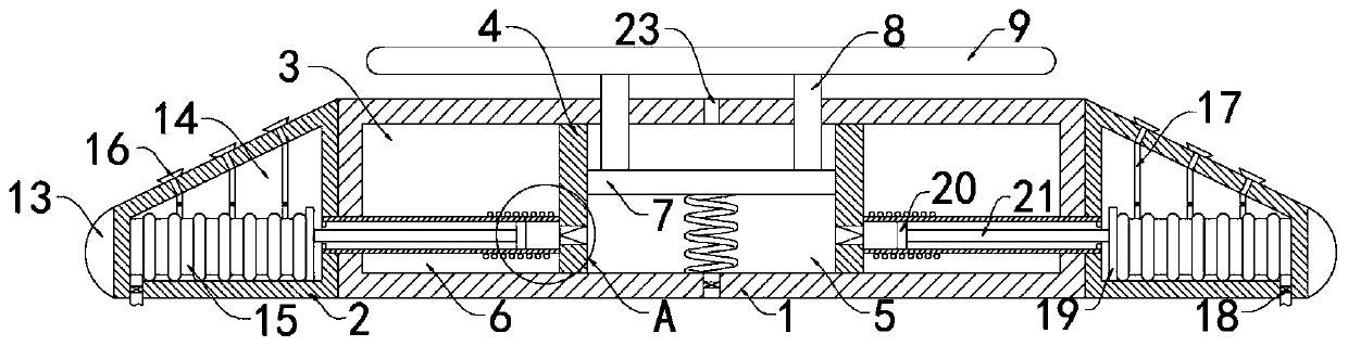
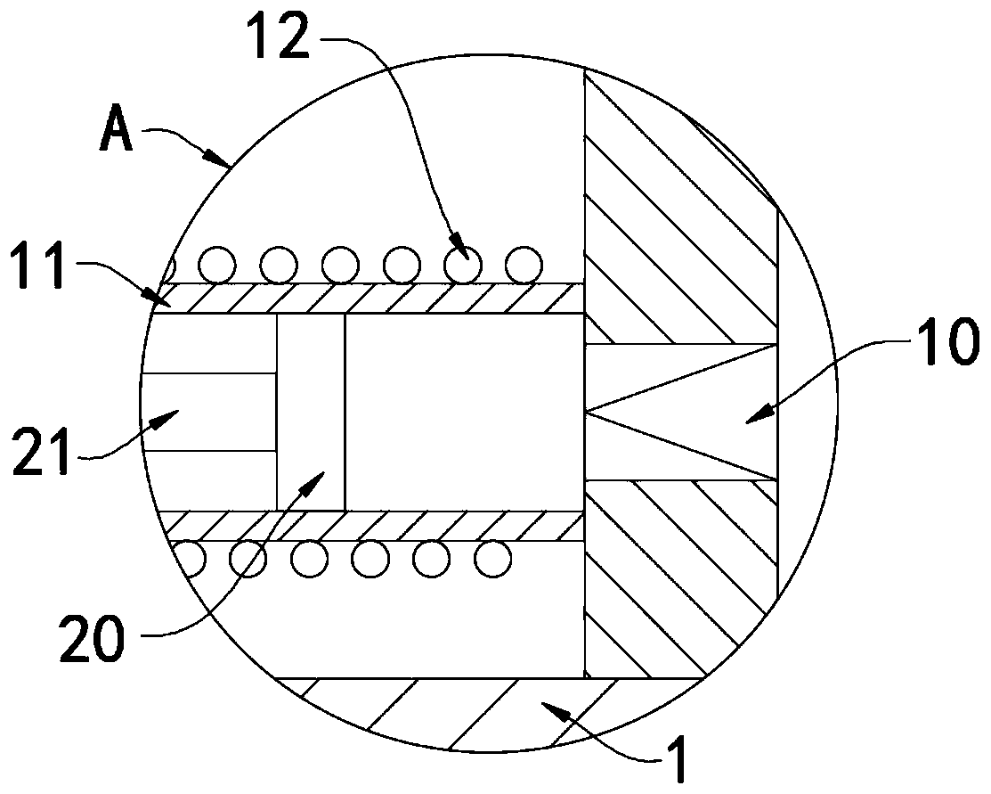
[0024] Such as Figure 1-3 As shown, a deceleration belt with a warning function includes a deceleration briquetting block 1, deceleration beading bars 2 are fixedly connected to the side walls on both sides of the deceleration briquetting block 1, and a cavity 3 is provided in the deceleration briquetting block 1, and the cavity 3 The internal fixed connection has two fixed plates 4 that are both vertically arranged. The two fixed plates 4 divide the cavity 3 into a deceleration chamber 5 located in the middle and a transmission chamber 6 located on both sides. The deceleration chamber 5 is sealed and slidably connected with a horizontal For the sliding plate 7 provided, it should be noted that the upper side wall of the deceleration briquetting block 1 is provided with a communication port 23 communicating with the deceleration chamber 5, and the communication hole 23 can balance the air pressure above the sliding plate 7, so that the sliding plate 7 can move up and down free...

Embodiment 2

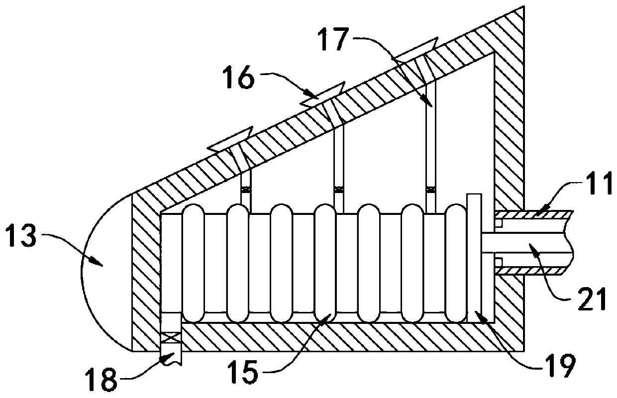
[0035] Such as Figure 4As shown, the difference between this embodiment and Embodiment 1 is that: the upper side wall of the deceleration bezel 2 is fixedly connected with a plurality of reflective strips 22, and a plurality of sprinkler heads 16 are arranged between the plurality of reflective strips 22 and are lower than the reflective strips. Bar 22 is set.

[0036] In this embodiment, the reflective strip 22 arranged on the side wall of the deceleration bead 2 can enable the driver to see the deceleration belt in advance at night, thereby decelerating as early as possible to ensure driving safety. The sprinkler head 16 is set lower than the reflective strip 22. When the automobile rolls on the deceleration bead 2, it will only contact the reflective strip 22, which can effectively protect the sprinkler head 16.


PUM


Abstract

The invention belongs to the field of traffic, in particular to a deceleration strip with a warning function. The deceleration strip includes a decelerating press block, wherein decelerating pressingstrips are fixedly connected to the side walls of the two sides of the decelerating pressing block; a cavity is formed in the decelerating pressing block; two vertically-arranged fixing plates are fixedly connected into the cavity; and the cavity is divided into a decelerating cavity located in the middle and transmission cavities located in the two sides through the two fixing plates, and a horizontally-arranged sliding plate is connected into the decelerating cavity in a sealed and sliding mode. As the deceleration strip is provided with a flow limiting valve, when an automobile slowly passes through the deceleration strip, the flow limiting valve in the fixing plate exhausts the gas in the decelerating cavity in the process, so as to enable the rolling plate to descend by a large height, and then the bumping feeling of a driver can be effectively relieved; and when an automobile runs quickly, due to the fact that the flow limiting valve cannot exhaust gas in the decelerating cavityeasily in a short time, the rolling plate cannot descend obviously, and the obvious bumping feeling can be brought to the driver, so that the automobile speed of the driver can be reduced, and the road safety can be improved.

Description

technical field [0001] The invention belongs to the traffic field, in particular to a speed bump with a warning function. Background technique [0002] The speed bump is a traffic facility installed on the road to slow down the passing vehicles. Generally speaking, it is a road belt that reduces the speed of the vehicle, which can greatly reduce the speed of the speeding car. It is often used in industrial and mining enterprises, campuses and residential quarters. It is one of the essential facilities in transportation. [0003] The setting of the speed reduction belt is to slow down the speed of the car when driving to a specific road section, so as to ensure traffic safety. However, this is not the case in reality. The existing speed reduction belt cannot effectively reduce the bumpy feeling when the vehicle is driving at a low speed, and it is easy to cause many drivers. Accelerating through the speed bump is a great safety hazard. Moreover, there is often a lot of dust ...

Claims


Application Information

Patent Timeline
Patent Type & Authority Applications(China)
IPC IPC(8): E01F9/50E01F9/529
CPCE01F9/50E01F9/529
Inventor 张飞航邵智勇
Owner 合肥慧问机械设计有限公司
Why Eureka
Try Eureka