Bagging machine for salt processing
A bagging machine and salt technology, applied in packaging, etc., can solve the problems of troublesome operation, easy drop of salt on the ground, high labor cost, etc., and achieve the effect of convenient operation, low labor cost, and convenient binding treatment
- Summary
- Abstract
- Description
- Claims
- Application Information
AI Technical Summary
Problems solved by technology
Method used
Image
Examples
Embodiment 1
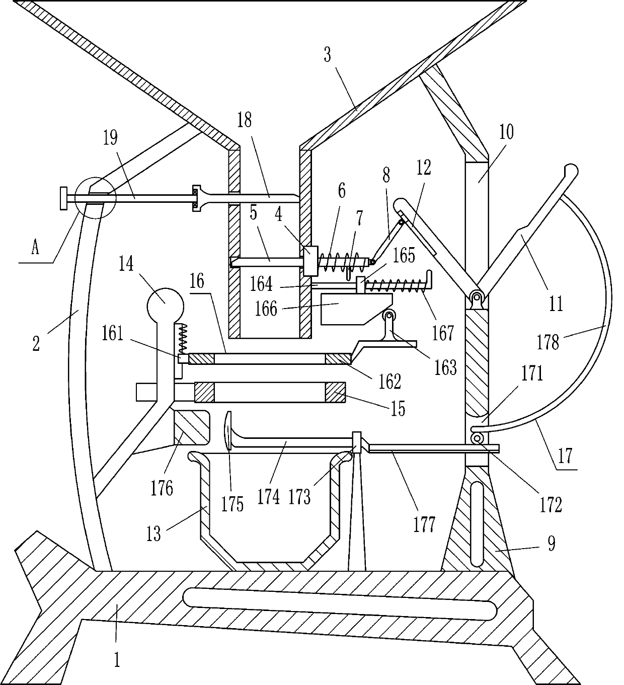
[0017] as attached figure 1 As shown, a bagging machine for salt processing includes a base 1, a support rod 2, a hopper 3, a first guide sleeve 4, a baffle plate 5, a first spring 6, a contact block 7, a connecting rod 8, and a support plate 9 , L-shaped rod 11, guide member 12, frame body 13, guide rod 14, fixed arc-shaped plate 15 and pressing mechanism 16, the left side of base 1 top is fixedly connected with support rod 2, and the top of support rod 2 is fixedly connected with The hopper 3 where the salt is placed, the lower part of the right side of the hopper 3 is embedded with the first guide sleeve 4, and the first guide sleeve 4 is slidingly provided with a baffle 5, and the left part of the baffle 5 is located in the hopper 3 to cooperate with it. The first spring 6 is wound between the right part of the plate 5 and the right side of the first guide sleeve 4, the right end of the baffle plate 5 is hinged with a connecting rod 8, the right side of the bottom of the b...
Embodiment 2
[0022] On the basis of embodiment one, as attached figure 1As shown, push mechanism 17 is also included, and push mechanism 17 includes gear 172, second guide sleeve 173, guide rod 174, push plate 175, fixed block 176, movable rack 177 and arc rack 178, support plate 9 The bottom part is provided with a through hole 171, and the middle of the through hole 171 is connected with a gear 172 in a rotating manner. A second guide sleeve 173 is installed on the right side of the top of the base 1, and the second guide sleeve 173 is located on the left side of the support plate 9. The second guide sleeve 173 Be provided with guide rod 174 inside, guide rod 174 left ends are fixedly connected with the push plate 175 that can be pushed bag, and guide rod 174 right ends are fixedly connected with movable rack 177, and movable rack 177 right part is positioned at gear 172 below and meshes with it, and pushes The fixed block 176 that the plate 175 cooperates is installed in the lower right...
Embodiment 3
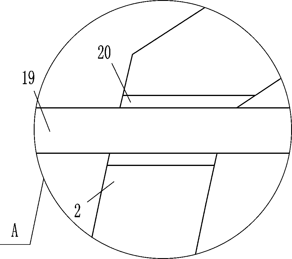
[0025] On the basis of embodiment one and embodiment two, as attached figure 1 And attached figure 2 Shown, also comprise baffle plate 18 and screw rod 19, the material baffle plate 18 of hopper 3 bottom left sliding type, support rod 2 tops have threaded hole 20, be provided with screw rod 19 in the threaded hole 20, the right end of screw rod 19 and The left side of the material retaining plate 18 is rotationally connected, and the screw rod 19 is connected with the material retaining plate 18 through a bearing seat.
[0026] First, the operator twists the screw rod 19 to reverse, and the screw rod 19 reversely moves to the left through the threaded hole 20, and the screw rod 19 moves to the left to drive the material retaining plate 18 to move to the left, and the material retaining plate 18 moves to the left to control the amount of salt dropped. Adjust, when the material baffle plate 18 moves to the position of demand to the left, stop twisting the screw rod 19, you can...
PUM
 Abstract
Description
Claims
Application Information
 - R&D
- Intellectual Property
- Life Sciences
- Materials
- Tech Scout
- Unparalleled Data Quality
- Higher Quality Content
- 60% Fewer Hallucinations
Browse by: Latest US Patents, China's latest patents, Technical Efficacy Thesaurus, Application Domain, Technology Topic, Popular Technical Reports.
© 2025 PatSnap. All rights reserved.Legal|Privacy policy|Modern Slavery Act Transparency Statement|Sitemap|About US| Contact US: help@patsnap.com


