
Magnetic coupling mechanism for wireless power supply of rail transit

A wireless power supply, rail transit technology, applied in the direction of collectors, electric vehicles, electrical components, etc., to achieve the effect of lightweight design, simplified modification procedures, and increased overall performance

Active Publication Date: 2020-03-06
CHINA CREC RAILWAY ELECTRIFICATION BUREAU GRP +2
View PDF5 Cites 3 Cited by
  • Summary
  • Abstract
  • Description
  • Claims
  • Application Information

AI Technical Summary

Problems solved by technology

[0004] Based on this, it is necessary to provide a magnetic coupling mechanism for rail transit wireless power supply to solve the problem of how to improve the operating performance of radio vehicles

Method used


Image

  • Magnetic coupling mechanism for wireless power supply of rail transit
  • Magnetic coupling mechanism for wireless power supply of rail transit
  • Magnetic coupling mechanism for wireless power supply of rail transit

Examples


Embodiment Construction

[0061] In order to make the above-mentioned purpose, features and advantages of the present application more obvious and understandable, the specific implementation manners of the present application will be described in detail below in conjunction with the accompanying drawings. In the following description, numerous specific details are set forth in order to provide a thorough understanding of the application. However, the present application can be implemented in many other ways different from those described here, and those skilled in the art can make similar improvements without departing from the connotation of the present application. Therefore, the present application is not limited by the specific implementation disclosed below.

[0062] The serial numbers assigned to components in this document, such as "first", "second", etc., are only used to distinguish the described objects, and do not have any sequence or technical meaning. The "connection" and "connection" ment...


PUM


Abstract

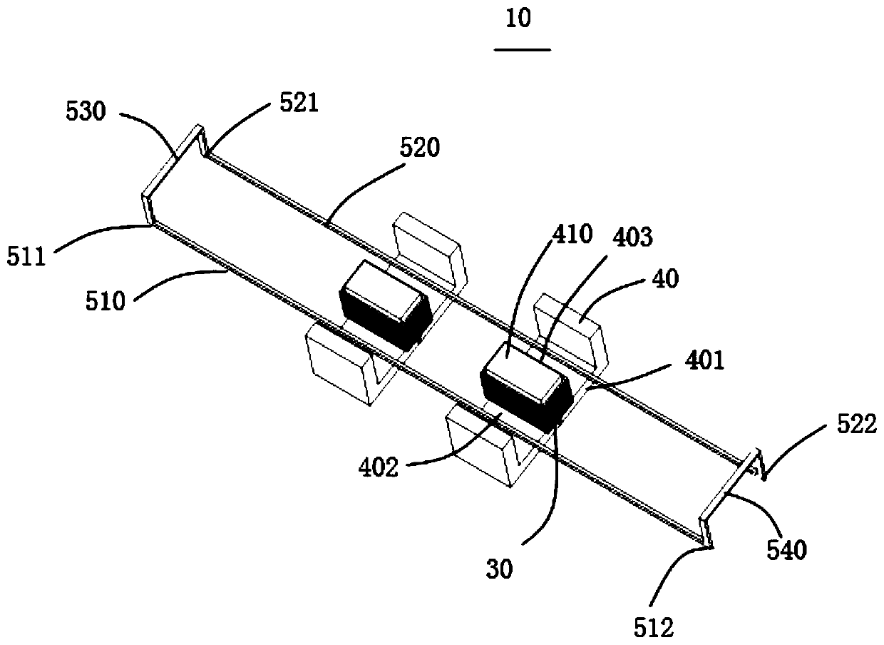
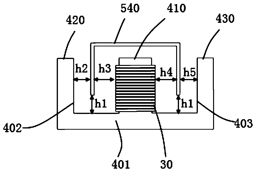
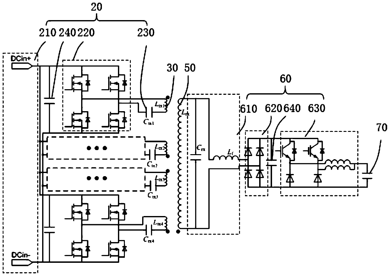
The present application relates to a magnetic coupling mechanism for wireless power supply of rail transit. The magnetic coupling mechanism includes a transmitting power source, a transmitting coil, amagnetic core, a receiving coil, a current adjustment circuit, and an energy storage device. The magnetic core includes a base body. A first boss is disposed on a surface of the base body. A first guide rail and a second guide rail are arranged on both sides of the first boss and are electrically connected to form a closed coil. The receiving end of the magnetic coupling mechanism for wireless power supply of rail transit is arranged on a tram. In the present application, the receiving end of the magnetic coupling mechanism uses a rail-type receiving coil instead of a flat receiving coil. With the same received magnetic flux, the rail-type receiving coil is smaller in metal volume and lighter. The rail-type receiving coil reduces the weight of the receiving end of the onboard magnetic coupling mechanism. Therefore, the magnetic coupling mechanism for wireless power supply of rail transit reduces the load of the tram, realizes a lightweight design, and improves the overall performanceof the tram.

Description

technical field [0001] The present application relates to the technical field of wireless power transmission, in particular to a magnetic coupling mechanism for rail transit wireless power supply. Background technique [0002] At present, the wireless charging of electric vehicles has been widely and maturely applied, mainly adopting the magnetic coupling wireless power transmission scheme. In the prior art, the magnetic coupling mechanism at the transmitting and receiving ends of the wireless power transmission structure adopts the form of a flat coil. The magnetic coupling mechanism at the receiving end is fixed on the vehicle body. [0003] Rail transit power supply needs more power, generally hundreds of kilowatts to several megawatts. The planar coil structure has larger volume and heavier weight. The weight of the planar coil structure increases the overall load on the vehicle and reduces the operational performance of the radio vehicle. Contents of the invention ...

Claims


Application Information

Patent Timeline
Patent Type & Authority Applications(China)
IPC IPC(8): H02J7/02H02J50/12H02J5/00
CPCH02J50/12
Inventor 蒋烨林云志陈凯楠檀添林秋琼赵争鸣赖一雄罗金
Owner CHINA CREC RAILWAY ELECTRIFICATION BUREAU GRP
Learn More