Power equipment installation insulating frame

A technology for electrical equipment and insulating racks, applied in the field of electrical equipment installation insulating racks, can solve problems such as incomplete functions, lack of overall stable placement of insulating racks, and lack of effective cleaning of accumulated dust.

Active Publication Date: 2020-03-06
STATE GRID SHANDONG ELECTRIC POWER +1
View PDF14 Cites 0 Cited by
  • Summary
  • Abstract
  • Description
  • Claims
  • Application Information

AI Technical Summary

Problems solved by technology

[0002] The insulating frame for installing electrical equipment is a frame that can be installed with electrical equipment. There are many insulating frames on the market, but they are incomplete and inconvenient to use. However, with the progress of the times, the insulating frame is gradually developing. trend
[0003] The existing insulating frame for installing electrical equipment does not have a mechanism that is convenient for the staff to overhaul the internal components of the cabinet at the top of the switchgear and does not have a mechanism that can stably place the insulating frame as a whole that can be applied to different uneven roads, and There is no mechanism for effectively cleaning the accumulated dust on the top of the switchgear, and there is no mechanism for fixing the switchgear and its insulating frame conveniently

Method used


Image

  • Power equipment installation insulating frame
  • Power equipment installation insulating frame
  • Power equipment installation insulating frame

Examples


Embodiment Construction

[0040] The following will clearly and completely describe the technical solutions in the embodiments of the present invention with reference to the accompanying drawings in the embodiments of the present invention. Obviously, the described embodiments are only some, not all, embodiments of the present invention. Based on the embodiments of the present invention, all other embodiments obtained by persons of ordinary skill in the art without creative efforts fall within the protection scope of the present invention.

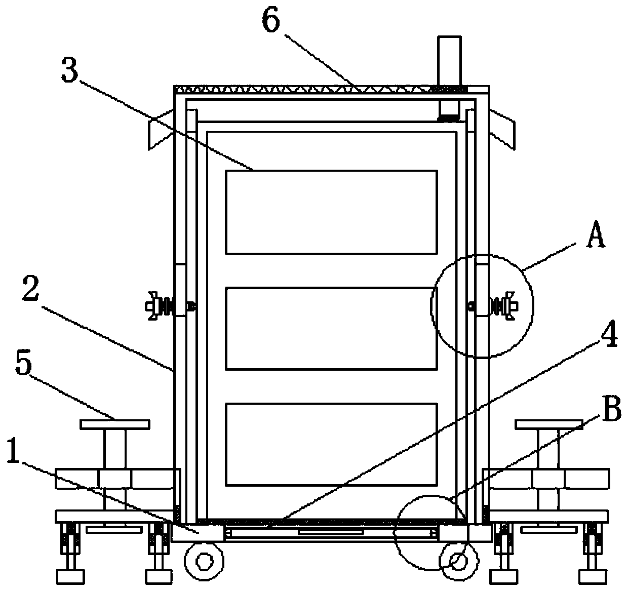
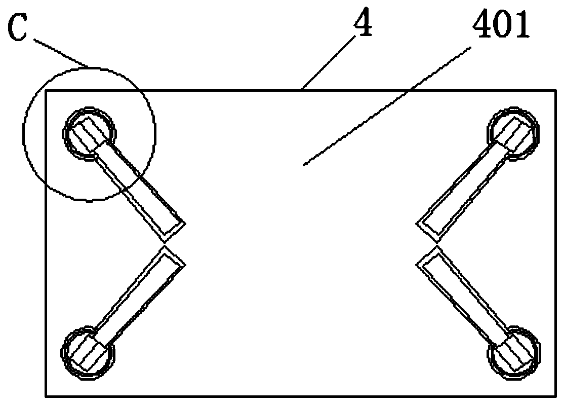
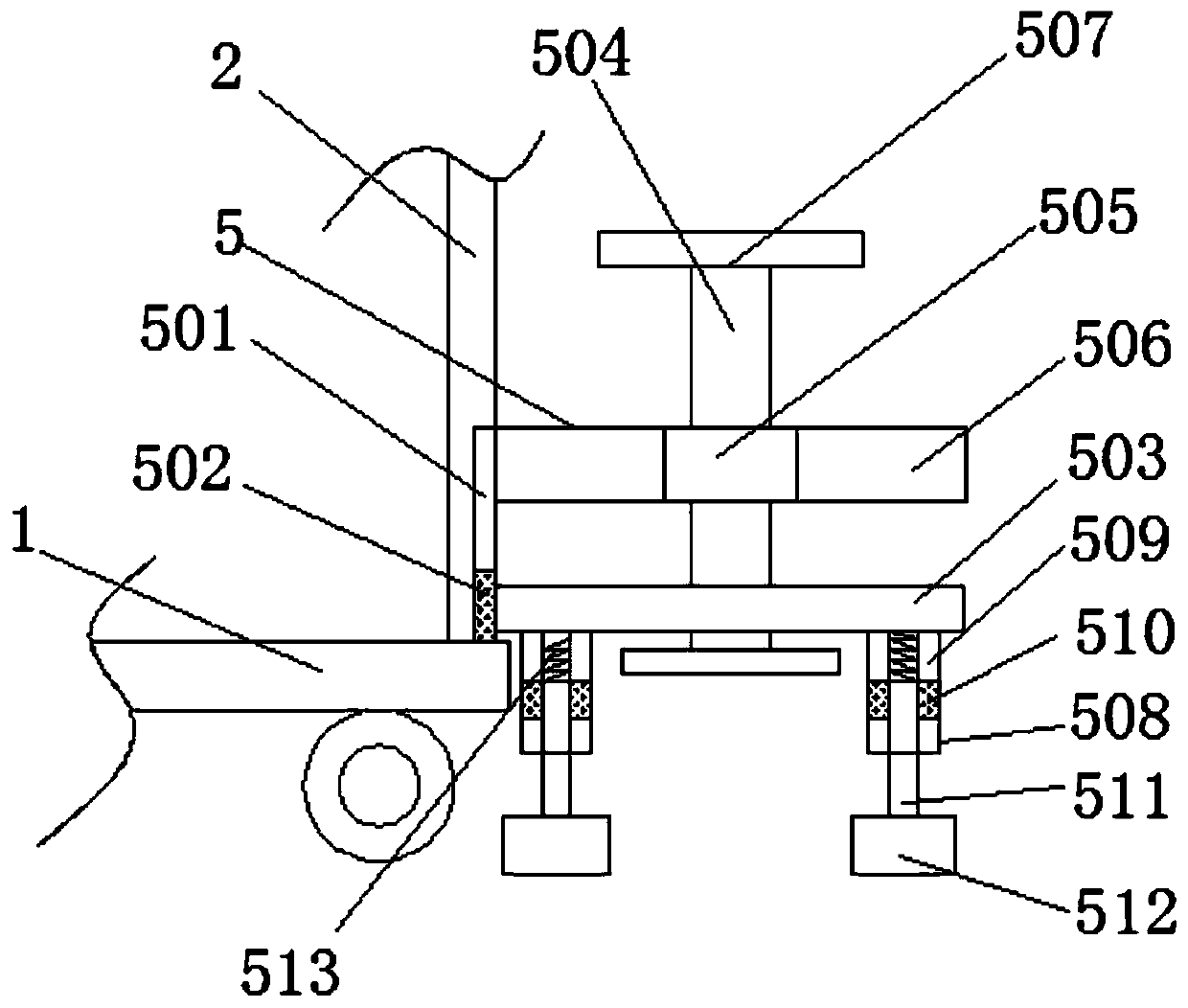
[0041] refer to Figure 1-7, power equipment installation insulation frame, including base plate 1, frame 2, switch cabinet 3, support mechanism 4, support plate 401, pulley 402, slide rail 403, placement groove 404, connecting block 405, arc slider 406, first slide Slot 407, first movable shaft 408, support column 409, adjustable mechanism 5, second chute 501, second slider 502, first support plate 503, external threaded rod 504, bearing 505, second support plate ...


PUM


Abstract

The invention discloses a power equipment installation insulating frame, which includes a bottom plate, wherein a frame is fixedly connected to the top of the bottom plate; a switchgear cabinet is installed inside the frame; a support mechanism is slidably connected to the inner side of the bottom plate; an adjustable mechanism is fixedly installed on the outer wall of the frame; and a cleaning mechanism is connected to the top of the frame. In the present invention, under the effect of the support mechanism, when a worker needs to overhaul the switchgear cabinet on a support frame, the support plate of the switchgear cabinet can be pulled out from the inside of the bottom plate along a slide rail by a pulley, and a support column connected to a first movable shaft connected to the bottomof a connection block in a circular stopping deep groove in an installation groove disposed on the bottom of a support plate of the switchgear cabinet can be rotated out of the long groove of the installation groove, and then the support column is rotated on a circular chute disposed on the inner wall of a circular groove through an arc-shaped slider connected the outside of the connection block,so that the support column is restricted by the circular stopping deep groove, and a vertical immovable state is formed between the support column and the support plate.

Description

technical field [0001] The invention specifically relates to an insulating frame for installing electric equipment. Background technique [0002] The insulating frame for installing electrical equipment is a frame that can be installed with electrical equipment. There are many insulating frames on the market, but they are incomplete and inconvenient to use. However, with the progress of the times, the insulating frame is gradually developing. trend. [0003] The existing insulating frame for installing electrical equipment does not have a mechanism to facilitate the maintenance of the internal components of the cabinet at the top of the switch cabinet by the staff, and does not have a mechanism that can stably place the insulating frame as a whole on different uneven road surfaces, and There is no mechanism for effectively cleaning the accumulated dust on the top of the switchgear, and there is no mechanism for conveniently fixing the switchgear and its insulating frame. ...

Claims


Application Information

Patent Timeline
Patent Type & Authority Applications(China)
IPC IPC(8): H02B1/30H02B1/54H02B1/52H02B1/50
Inventor 朱礼桦孙钦国王明强费源
Owner STATE GRID SHANDONG ELECTRIC POWER
Why Eureka
Try Eureka