Gas turbine combustor
A gas turbine and burner technology, which is applied to combustion chambers, combustion methods, combustion equipment, etc., can solve the problems of complex fuel paths, fuel cannot be evenly distributed, etc., and achieves easy assembly and disassembly, simplified supply paths, and improved uniformity. Effect
- Summary
- Abstract
- Description
- Claims
- Application Information
AI Technical Summary
Problems solved by technology
Method used
Image
Examples
no. 1 Embodiment
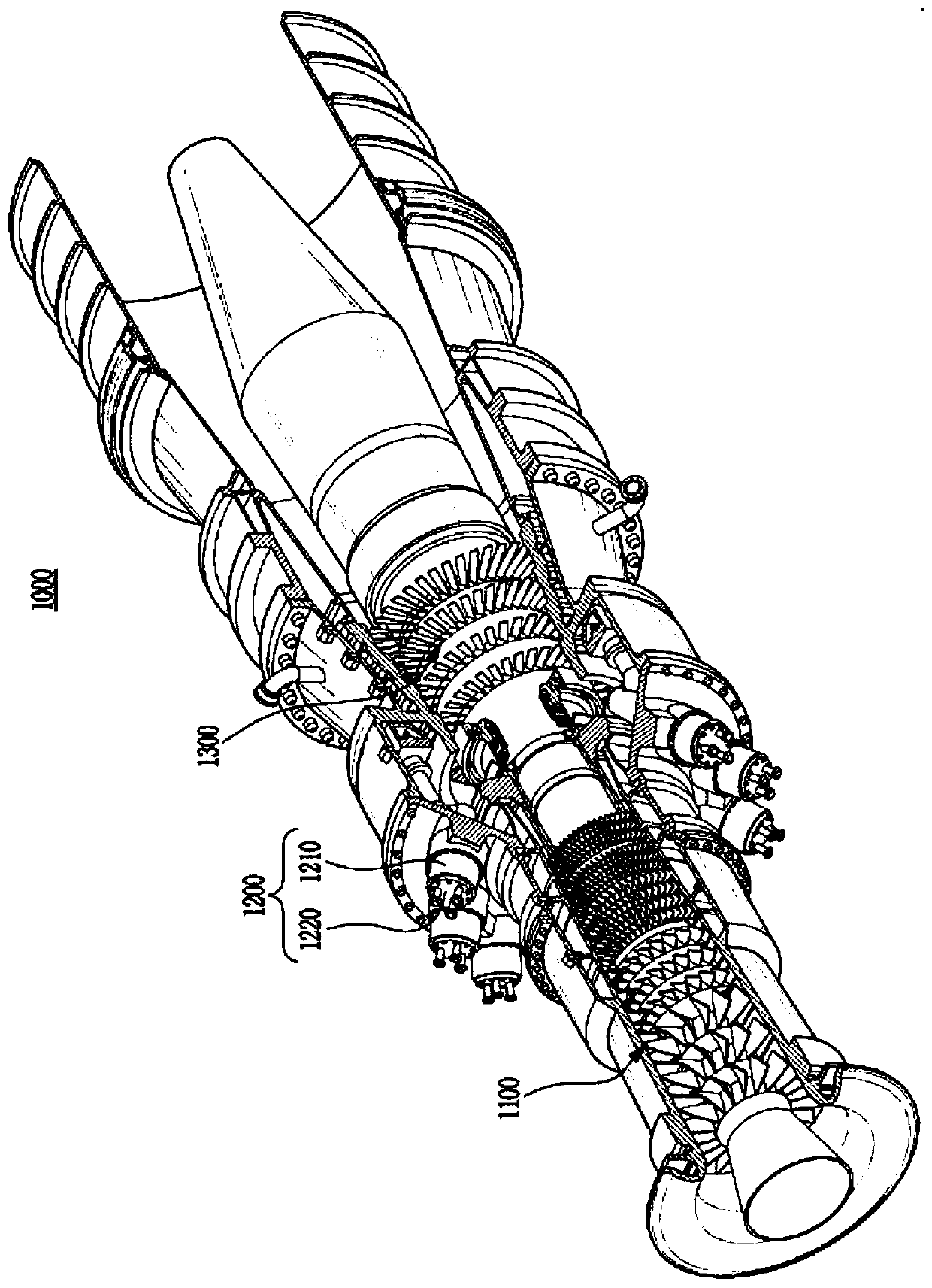
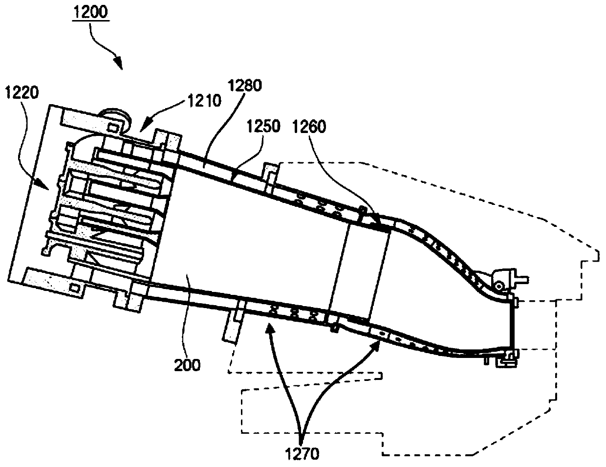
[0088] On the one hand, the burner 1200 according to the first embodiment of the present invention includes: a nozzle part 100 which mixes and injects fuel and air; and a combustion chamber 200 which combusts the premixed gas injected by the nozzle part 100 .
[0089] like image 3 As shown, the above-mentioned nozzle part 100 has a cylindrical shape, including: a nozzle part housing 102, which forms an overall appearance; a plurality of nozzles 300, which inject a mixture of fuel and air; a nozzle housing 400, which is formed for inserting the above an opening of the nozzle 300 ; and a fuel supply part 500 for supplying fuel to the above-mentioned nozzle 300 .
[0090] like Figure 4 As shown, the nozzle unit 100 is radially divided into a plurality of regions. In addition, each of the divided areas includes one nozzle 300 described above. That is, the number of regions is divided so as to match the number of nozzles 300 described above, and each region is formed in a fan ...
no. 2 Embodiment
[0128] On the one hand, according to Figure 8b and Figure 9b In the shown second embodiment of the present invention, in the above-mentioned nozzle housing 400', the fuel chamber is located on the upper side of the figure, and the air chamber having a predetermined thickness is located on the lower side. That is, the locations of the fuel chamber and the air chamber are spaced apart from each other with no housing parts in the space between them.
[0129] The structure and function of the fuel chamber in the second embodiment are the same as those in the first embodiment. However, when the second embodiment is compared with the first embodiment, the height of the air cavity is reduced, and it is located only in a part of the lower side of the nozzle part 100 . At this time, in the air cavity of the second embodiment, not only the first opening 422' is formed on the outer peripheral surface, but also the second opening 404' is formed along the axial direction facing the noz...
no. 3 Embodiment
[0135] On the one hand, according to Figure 8c and Figure 9c In the third embodiment of the present invention shown, the fuel chamber portion of the nozzle housing 400" is formed into a ring corresponding to the above-mentioned nozzle 300. This is different from the shape of the fuel chamber having a fan-shaped cross section in the first and second embodiments. And therefore the overall volume of the fuel chamber can be reduced.
[0136] In addition, the first opening 422'' and the second opening 404'' formed in the air cavity are the same as those described in the second embodiment above.
[0137] The effect according to the third embodiment of the present invention is as follows.
[0138] The fuel chamber of the third embodiment has a circular cross-section instead of a fan-shaped cross-section, so that uniform fuel distribution in the entire circumferential direction can be expected. Although there may be a slight difference in the flow of air, similar effects to those...
PUM
 Abstract
Description
Claims
Application Information
 - Generate Ideas
- Intellectual Property
- Life Sciences
- Materials
- Tech Scout
- Unparalleled Data Quality
- Higher Quality Content
- 60% Fewer Hallucinations
Browse by: Latest US Patents, China's latest patents, Technical Efficacy Thesaurus, Application Domain, Technology Topic, Popular Technical Reports.
© 2025 PatSnap. All rights reserved.Legal|Privacy policy|Modern Slavery Act Transparency Statement|Sitemap|About US| Contact US: help@patsnap.com


