
Continuous rolling mill vibration signal separation method based on sparse feature similarity

A vibration signal, sparse feature technology, applied to vibration measurement in solids, measurement vibration, measurement devices, etc., can solve algorithm failure, poor estimation accuracy and robustness, and can not meet the independence assumption of independent component analysis algorithm. and other problems to achieve the effect of improving accuracy and filtering out interference noise.

Active Publication Date: 2020-02-28
WUHAN UNIV OF SCI & TECH
View PDF16 Cites 3 Cited by
  • Summary
  • Abstract
  • Description
  • Claims
  • Application Information

AI Technical Summary

Problems solved by technology

However, there is a defect in the above-mentioned patent: in engineering applications, there are often cross-frequency components between mechanical vibration sources, which makes it impossible to satisfy the independence assumption of the independent component analysis algorithm, thus causing the algorithm to fail
However, this method has shortcomings: when fitting the clustering lines of each vibration source through the time-frequency scatter diagram and then calculating the mixing matrix, the estimation accuracy and robustness of the direction of the line are often poor due to noise interference , a good estimate of the mixing matrix cannot be reached

Method used


Image

  • Continuous rolling mill vibration signal separation method based on sparse feature similarity
  • Continuous rolling mill vibration signal separation method based on sparse feature similarity
  • Continuous rolling mill vibration signal separation method based on sparse feature similarity

Examples


Embodiment 1

[0077] Vibration signals of 4-stand continuous rolling mills (including 4 continuous rolling mills) are collected by acceleration sensors, and a vibration signal separation method of continuous rolling mills based on sparse feature similarity of the present invention is applied to effectively separate the vibration signals.

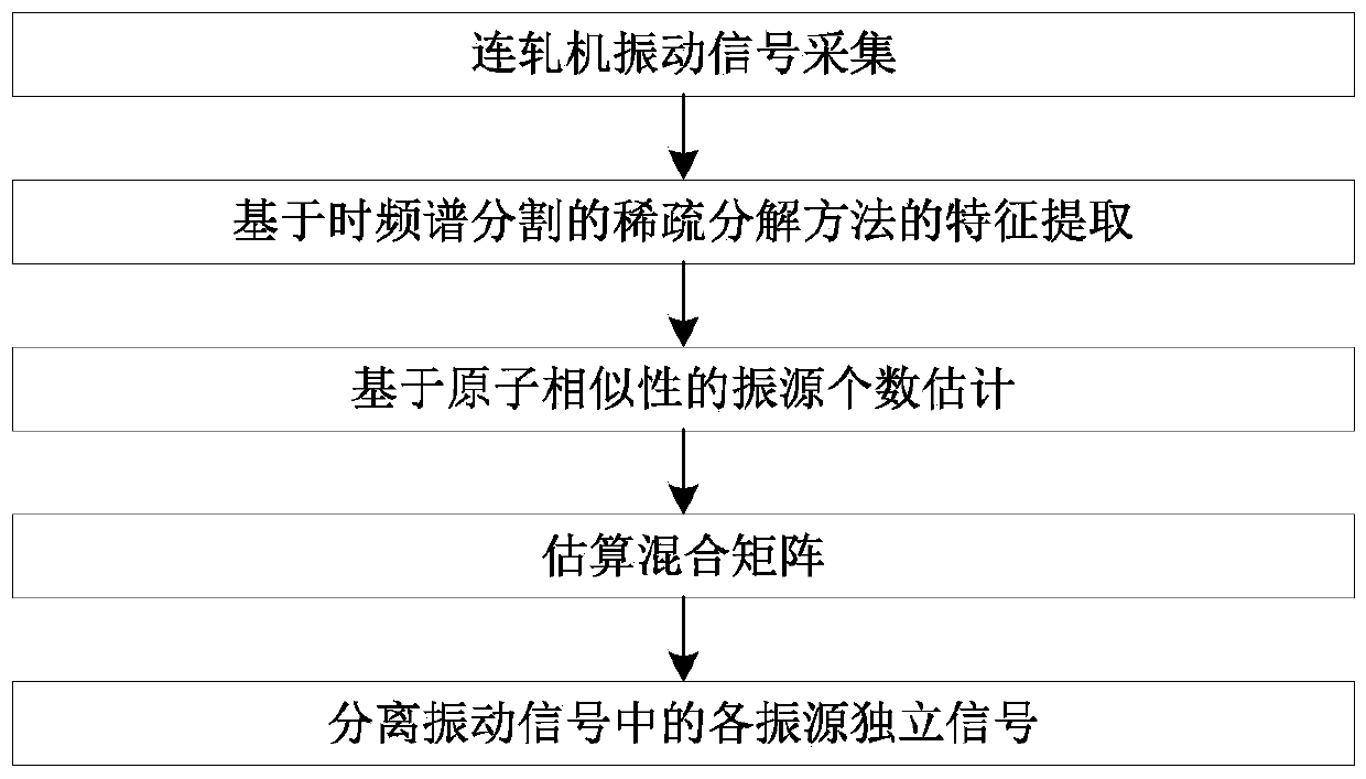
[0078] like figure 1 As shown, the specific method steps are as follows:

[0079] (1) Collect the vibration signal of the continuous rolling mill through the acceleration sensor:

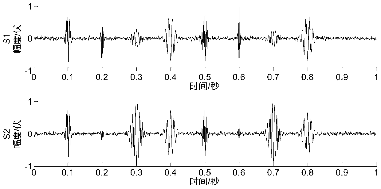
[0080] Acceleration sensors are respectively arranged on the lower work roll chocks (two observation points) of the two continuous rolling mills F1 and F2 in the continuous rolling unit to collect the vibration signals of each vibration source when the rolling mill rolls steel; figure 2 Shown are the observation signals of the two channels (two sets of observation signals) collected at the above two observation points respectively, where S 1 is the vibration signal collected...


PUM


Abstract

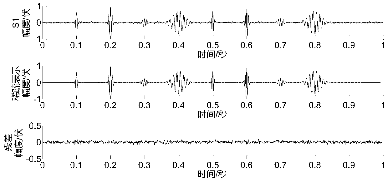
The invention discloses a continuous rolling mill vibration signal separation method based on sparse feature similarity. The continuous rolling mill vibration signal separation method comprises the steps of: arranging acceleration sensors at one or more different positions on the surface of a sensitive part of a rotating component of a continuous rolling mill, and acquiring vibration signals, namely observation signals, of each vibration source during operation; acquiring sparse representation of each path of acquired vibration signals under an optimal atom set by adopting a sparse feature extraction method based on time-frequency spectrum segmentation; then clustering all atoms extracted through sparse representation according to structural similarity, estimating a number of vibration sources, and updating a sparse representation result by adopting the atoms corresponding to each clustering center; and finally, estimating a hybrid matrix based on a clustering coefficient correspondingto the new sparse representation result, and further calculating an independent signal of each vibration source to realize separation of vibration signals of the continuous rolling mill. According tothe continuous rolling mill vibration signal separation method, interference noise of the continuous rolling mill in the operation process can be effectively filtered out, the precision of sparse feature extraction is improved, and the number of vibration sources and the hybrid matrix can be estimated more precisely.

Description

technical field [0001] The invention belongs to the technical field of state monitoring and fault diagnosis of rotating machinery, and relates to a method for separating vibration signals of a multi-stand continuous rolling mill, in particular to a method for separating vibration signals of a continuous rolling mill based on sparse feature similarity. Background technique [0002] In the strip production process of metallurgical enterprises, the rough rolling unit and the finishing rolling unit are the core equipment of the entire rolling process. The working status of the bearings and rolls in these continuous rolling units will directly determine the quality accuracy and performance indicators of the rolled products. During the long-term continuous and high-intensity work of the continuous rolling mill unit, failures such as cracks on the surface of the roll, partial peeling of the surface of the roll, and failure of the support bearing of the roll often occur, which will a...

Claims


Application Information

Patent Timeline
Patent Type & Authority Applications(China)
IPC IPC(8): G01H1/12
CPCG01H1/12
Inventor 严保康周凤星马娅婕卢少武但峰宁博文胡轶
Owner WUHAN UNIV OF SCI & TECH
Learn More