
Carbon dioxide thermoelectric energy storage device and control method thereof

A technology for carbon dioxide and energy storage devices, applied in pump devices, steam engine devices, refrigerators, etc., can solve the problems of reducing system thermal efficiency, system energy storage efficiency, and high entropy loss of expanders, and achieve economic benefits and high-efficiency thermoelectricity. Storage and transformation, the effect of reducing entropy loss

Active Publication Date: 2020-02-28
XI AN JIAOTONG UNIV
View PDF8 Cites 5 Cited by
  • Summary
  • Abstract
  • Description
  • Claims
  • Application Information

AI Technical Summary

Problems solved by technology

[0003] 1) The current system uses an expander to reduce the pressure and temperature of the working fluid during the energy storage process and complete the cycle of the working medium. The expander has problems such as high entropy loss, which will lead to a decrease in the energy storage efficiency of the system
[0004] 2) In the current system, if the turbine back pressure is too low and the working fluid enters the two-phase region, it cannot be condensed by normal temperature water during the energy release process, and must use a lower temperature cold medium such as ice-water mixture to condense, so that the thermal power storage The energy system must have a cold storage medium, which will increase the operating cost; if the turbine back pressure is too high and the working fluid does not enter the two-phase region, the thermal efficiency of the system will be reduced
In summary, both of these situations will reduce the economic benefits of the system

Method used


Image

  • Carbon dioxide thermoelectric energy storage device and control method thereof
  • Carbon dioxide thermoelectric energy storage device and control method thereof

Examples


Embodiment Construction

[0051] In order to make the purpose, technical effects and technical solutions of the embodiments of the present invention more clear, the technical solutions in the embodiments of the present invention are clearly and completely described below in conjunction with the accompanying drawings in the embodiments of the present invention; obviously, the described embodiments It is a part of the embodiment of the present invention. Based on the disclosed embodiments of the present invention, other embodiments obtained by persons of ordinary skill in the art without making creative efforts shall all fall within the protection scope of the present invention.

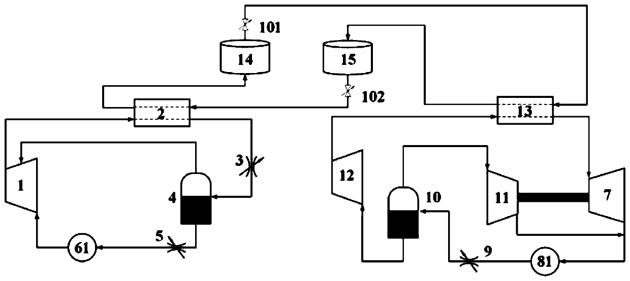
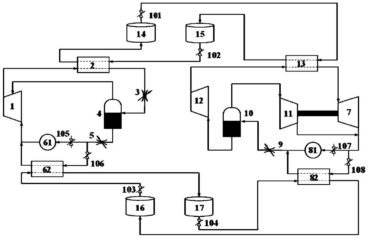
[0052] see figure 1 , a carbon dioxide thermoelectric energy storage device according to an embodiment of the present invention, comprising: an energy storage compressor 1, an energy storage heat exchanger 2, a first energy storage throttling expansion valve 3, an energy storage gas-liquid separator 4, a second energy storage ...


PUM


Abstract

The invention discloses a carbon dioxide thermoelectric energy storage device and a control method thereof. The carbon dioxide thermoelectric energy storage device comprises an energy storage part andan energy releasing part. The carbon dioxide thermoelectric energy storage device is provided with a plurality of energy storage throttle expansion valves used for throttle expansion of a working medium to realize cooling and depressurizing. The throttle valves are adopted to replace acting-free expansion turbines, entropy loss of a system can be reduced, and accordingly, the thermoelectric storage efficiency of carbon dioxide circulation is improved. During circulation, a gas-liquid separator is added, the circulation structure is changed, an outlets of an acting turbine does not reach a two-phase region, and the working medium is condensed through a normal-temperature medium and expanded through the throttle valves and then goes into the two-phase region so that the working medium can be condensed by the normal-temperature medium during energy releasing and circulating to strip off a cold storage component. The system cost is reduced. Meanwhile, the carbon dioxide thermoelectric energy storage device can ensure that the system efficiency does not drop during the process.

Description

technical field [0001] The invention belongs to the technical field of peak regulation energy storage devices and control, and in particular relates to a carbon dioxide thermoelectric energy storage device and a control method thereof. Background technique [0002] Energy storage technology is one of the key research directions in the future energy field. Existing energy storage technologies include pumped hydro storage, compressed air energy storage and electrochemical energy storage, etc., but pumped hydro storage has problems such as terrain restrictions; compressed air energy storage There are problems such as low energy storage efficiency and low energy density; electrochemical energy storage has problems such as scale and grade restrictions. In response to these problems, thermoelectric energy storage systems based on carbon dioxide cycles have gradually developed, but there are still some problems: [0003] 1) The current system uses an expander to reduce the pressur...

Claims


Application Information

Patent Timeline
Patent Type & Authority Applications(China)
IPC IPC(8): F25B9/00F25B31/00F25B39/00F25B41/04F25B43/00F28D20/00F01K25/10F04B23/04F25B41/20
CPCF25B9/008F25B31/00F25B39/00F25B43/00F28D20/00F04B23/04F01K25/103F28D2020/0082F25B41/20Y02E60/14
Inventor 谢永慧孙磊张荻
Owner XI AN JIAOTONG UNIV
Learn More