
A quasi-zero-stiffness vibration isolator with semi-circular slide rail

A quasi-zero-stiffness, semi-circular technology, which is applied in the field of semi-circular slide-rail type quasi-zero-stiffness vibration isolators, can solve problems such as bridge damage, excessive static deformation and instability of the vibration isolation system

Active Publication Date: 2020-11-06
NORTHEASTERN UNIV LIAONING
View PDF10 Cites 0 Cited by
  • Summary
  • Abstract
  • Description
  • Claims
  • Application Information

AI Technical Summary

Problems solved by technology

[0002] In actual engineering production, cyclical changes in physical state or reciprocating motion of objects, that is, vibration, are common. In most cases, vibration is not beneficial, such as bridge damage caused by noise, earthquakes, and resonance, and train wheel rail collision vibration. These vibrations will cause certain harm and inconvenience to scientific research, production activities and daily life.
At present, in linear vibration isolation systems, better vibration isolation performance is generally obtained by minimizing the natural frequency in the system, but this method will reduce the total stiffness of the vibration isolation system or be isolated The increase in mass will affect the bearing capacity of the vibration isolation system, causing excessive static deformation or instability of the vibration isolation system

Method used


Image

  • A quasi-zero-stiffness vibration isolator with semi-circular slide rail
  • A quasi-zero-stiffness vibration isolator with semi-circular slide rail
  • A quasi-zero-stiffness vibration isolator with semi-circular slide rail

Examples


Embodiment Construction

[0036] In order to make the purpose, technical solutions and advantages of the present invention clearer, the technical solutions in the embodiments of the present invention will be described in more detail below with reference to the drawings in the preferred embodiments of the present invention. In the drawings, the same or similar reference numerals denote the same or similar elements or elements having the same or similar functions throughout. The described embodiments are some, but not all, embodiments of the invention. The embodiments described below by referring to the figures are exemplary and are intended to explain the present invention and should not be construed as limiting the present invention. Based on the embodiments of the present invention, all other embodiments obtained by persons of ordinary skill in the art without creative efforts fall within the protection scope of the present invention. Embodiments of the present invention will be described in detail b...


PUM


Abstract

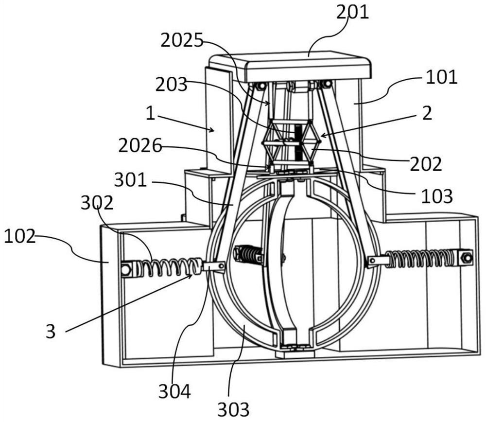
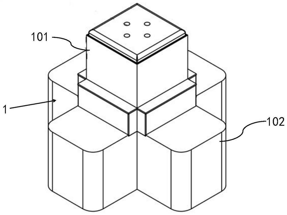
The invention discloses a semicircular slide rail type quasi-zero stiffness vibration isolator. Positive stiffness is provided by vertically arranging a first spring on the connecting rod assembly on the positive stiffness mechanism, and then by connecting the first spring on the positive stiffness mechanism. The load-bearing platform is connected to the negative stiffness mechanism through the positive and negative stiffness connecting rods, and the positive stiffness mechanism is connected to the inner wall of the lower frame. The negative stiffness mechanism is connected to the positive stiffness mechanism through the rotating pair formed between the positive and negative stiffness connecting rods and the second spring. The mechanisms are connected in parallel, so that the dynamic stiffness of the present invention at the equilibrium position is zero and has an extremely low resonance frequency, which improves the vibration isolation performance of low-frequency vibration. At the same time, by selecting the appropriate stiffness of the first spring and the second spring, Shift the force transfer rate curve to the left, reduce the initial vibration isolation frequency and expand the vibration isolation frequency bandwidth, so that the low-frequency vibration isolation performance of the vibration isolator can be improved. In short, the vibration isolator provided by the present invention has high static stiffness and low dynamic stiffness characteristics. and large vibration isolation bandwidth, which can be widely used in low-frequency vibration control.

Description

technical field [0001] The invention belongs to the technical field of vibration isolators, in particular to a semicircular slide rail type quasi-zero stiffness vibration isolator. Background technique [0002] In actual engineering production, cyclical changes in physical state or reciprocating motion of objects, that is, vibration, are common. In most cases, vibration is not beneficial, such as bridge damage caused by noise, earthquakes, and resonance, and train wheel rail collision vibration. These vibrations will cause certain harm and inconvenience to scientific research, production activities and daily life. At present, in linear vibration isolation systems, better vibration isolation performance is generally obtained by minimizing the natural frequency in the system, but this method will reduce the total stiffness of the vibration isolation system or be isolated The increase in mass will affect the bearing capacity of the vibration isolation system, causing excessive...

Claims


Application Information

Patent Timeline
Patent Type & Authority Patents(China)
IPC IPC(8): F16F13/00
CPCF16F13/005F16F2228/06
Inventor 于永恒姚国李常有武志花周雁迅邵国庆谢政播刘子嘉
Owner NORTHEASTERN UNIV LIAONING
Learn More