A transport mechanism in the field of packaging

A transportation mechanism and technology in the field, applied in packaging, conveyors, mechanical conveyors, etc., can solve the problems of low transportation efficiency and inconvenient applicability, and achieve the effect of good applicability and convenient use

Active Publication Date: 2021-04-30
杭州绿一环保技术有限公司
View PDF8 Cites 0 Cited by
  • Summary
  • Abstract
  • Description
  • Claims
  • Application Information

AI Technical Summary

Problems solved by technology

[0003] At present, the transportation mechanism is commonly used in the packaging field. The transportation mechanism based on the connecting rod is listed in Section 5.2 of the Mechanical Design Practical Mechanism and Device Atlas. After moving to the upper side, there is no wear in the vertical direction. This design is not easy to damage the surface of the cargo due to wear, and has a good effect; it finally realizes the law of transportation swing through the precisely designed cam and linkage mechanism; but the When the mechanism adjusts the trajectory, it needs to reset the cam and connecting rod, which makes the applicability of this mechanism inconvenient
[0004] In addition, when the existing connecting rod transports the goods, the speed of pushing the goods is basically the same as or not much different from the reset speed of the push plate, which makes the conveying efficiency low

Method used


Image

  • A transport mechanism in the field of packaging
  • A transport mechanism in the field of packaging
  • A transport mechanism in the field of packaging

Examples


Embodiment Construction

[0047] The specific implementation manners of the present invention will be further described in detail below in conjunction with the accompanying drawings and embodiments. The following examples or drawings are used to illustrate the present invention, but not to limit the scope of the present invention.

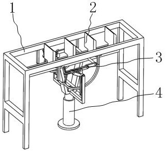
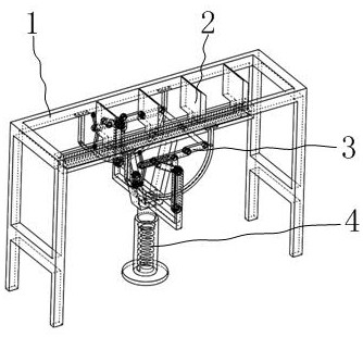
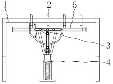
[0048] like figure 1 , 2 , 3, it includes a bracket 1, an adjustment mechanism 3, a base 4, a mounting slide bar 5, a trigger plate 27, and a guide rail 12, wherein as Figure 13 As shown, trigger plate 27 is made up of arc trigger plate 29 and lift trigger plate 30 two parts, as figure 1 , 4 , 5, two trigger plates 27 are symmetrically fixedly installed on both sides of the bracket 1; as Figure 6 As shown, the base 4 is a telescopic structure, and the inner side of the base 4 is equipped with a return spring 7, and the return spring 7 has a reset effect on the adjustment mechanism 3 installed on the base 4; Figure 5 As shown, the lower end of the base 4 is fixedly ...


PUM


Abstract

The invention belongs to the technical field of conveying mechanism, and in particular relates to a conveying mechanism in the field of packaging, which includes a bracket, an adjustment mechanism, a base, a mounting slide bar, a trigger plate, and a guide rail. The transmission of the plate and the rocker makes the sliding speed of the installation slide bar relatively slow when the installation slide bar pushes the goods forward through the conveying push plate installed on it, and when the installation slide bar drives the conveying push plate to reset and slide backward When installing the sliding bar, the sliding speed is relatively fast. On the one hand, pushing the goods forward slowly can reduce the friction damage of the goods. Efficiency, increasing the quantity of goods pushed per unit time.

Description

[0001] Technical field [0002] The invention belongs to the technical field of conveying mechanisms, and in particular relates to a conveying mechanism in the packaging field. Background technique [0003] At present, the transportation mechanism is commonly used in the packaging field. The transportation mechanism based on the connecting rod is listed in Section 5.2 of the Atlas of Mechanical Design Practical Mechanisms and Devices. After moving to the upper side, there is no wear in the vertical direction. This design is not easy to damage the surface of the cargo due to wear, and has a good effect; it finally realizes the law of transportation swing through the precisely designed cam and linkage mechanism; but the When the mechanism adjusts the trajectory, the cam and the connecting rod need to be reset, which makes the applicability of this mechanism inconvenient. [0004] In addition, when the existing connecting rod transports the goods, the speed of pushing the goods ...

Claims


Application Information

Patent Timeline
Patent Type & Authority Patents(China)
IPC IPC(8): B65B35/20
CPCB65G35/00B65G47/24B65G47/82
Inventor 马艳王益之赖江耀
Owner 杭州绿一环保技术有限公司
Why Eureka
Try Eureka