
Rotating disc type watch glass lens detector

A glass lens and testing machine technology, which is applied to measuring devices, optical testing of flaws/defects, material analysis by optical means, etc., can solve the problems of unsuitable watch glass lens turning over, unsuitable watch glass lens testing machine, etc. Achieve the effect of high degree of automation and low labor intensity

Active Publication Date: 2020-02-28
心鉴智控(深圳)科技有限公司
View PDF14 Cites 2 Cited by
  • Summary
  • Abstract
  • Description
  • Claims
  • Application Information

AI Technical Summary

Problems solved by technology

The above-mentioned patents are mainly applied to larger glass plates, and are not suitable for turning over watch glass lenses, let alone for use on watch glass lens inspection machines, and this patent adopts the form of single-stage flipping, although it also uses "Rotate the glass piece from the horizontal position around the rotating shaft to the vertical position." However, when the glass piece is in the vertical position, the direction of the detection head of the turntable watch glass lens inspection machine is facing one direction, so it can only be carried out in one direction. testing, and the front side of the glass plate of this patent is horizontal, while the back side is upright, facing two directions, so it is not suitable for use on the watch glass lens inspection machine, and it is necessary to develop a special flipper for watch glass lenses installation

Method used


Image

  • Rotating disc type watch glass lens detector
  • Rotating disc type watch glass lens detector
  • Rotating disc type watch glass lens detector

Examples


Embodiment Construction

[0039] In order to enable those skilled in the art to better understand the technical solution of the present invention, the present invention will be described in further detail below in conjunction with the accompanying drawings and specific embodiments. And the features in the embodiments can be combined with each other.

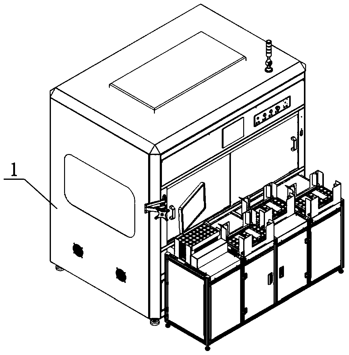
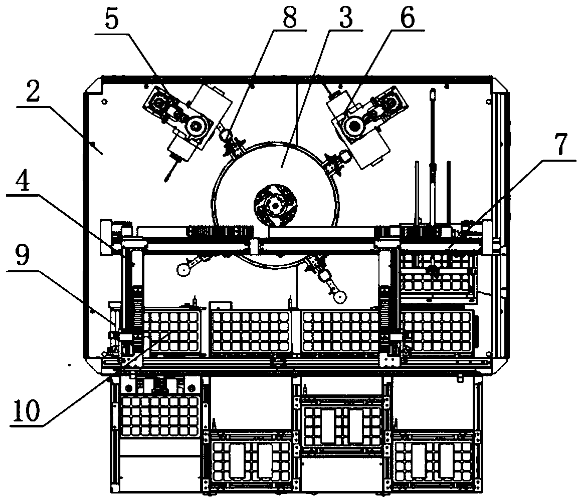
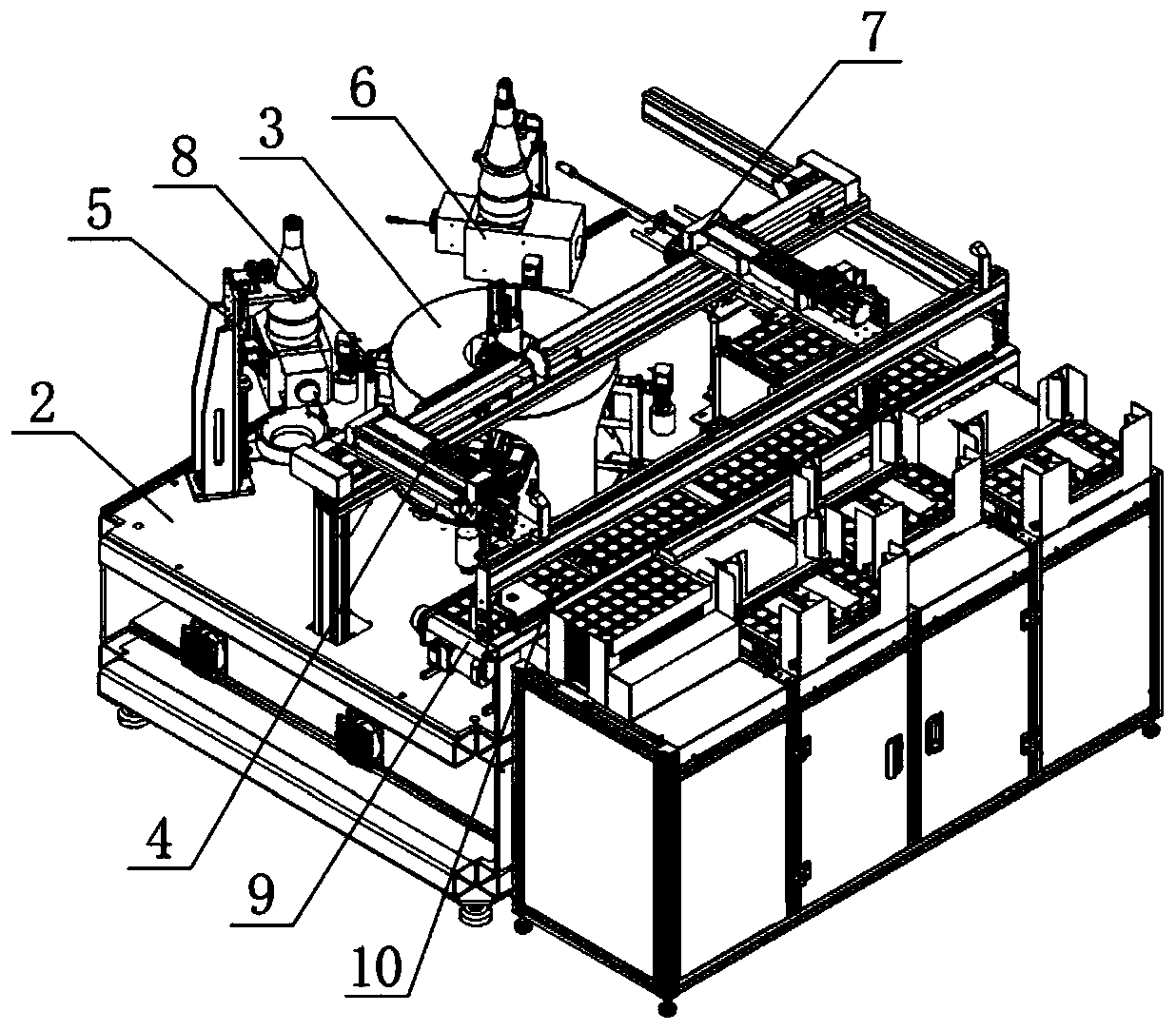
[0040] like figure 1 , 2 As shown in . Component 5, lens reverse detection camera component 6, unloading manipulator 7, material tray conveyor belt 9 and material tray 10, workbench 2 is set in box body 1, intermittent turntable 3 is installed on workbench 2, multiple lenses are turned over The surface adsorption carrier 8 is distributed and installed on the intermittent turntable 3, and the loading manipulator 4, the lens front detection camera assembly 5, the lens back detection camera assembly 6 and the unloading manipulator 7 are distributed on the intermittent turntable 3 in sequence, and the material tray The conveyor belt 9 is set on one side of...


PUM


Abstract

The invention discloses a rotating disc type watch glass lens detector. The rotating disc type watch glass lens detector comprises an intermittent rotating disc, a plurality of lens turn-over and suction loading tables, a feeding manipulator, a lens front surface detection camera assembly, a lens back surface detection camera assembly and a discharging manipulator; the plurality of lens turn-overand suction loading tables are distributed and mounted on the intermittent rotating disc; a watch glass lens is placed onto the lens turn-over and suction loading table by the feeding manipulator; theintermittent rotating disc rotates one station; after the lens front detection camera assembly detects and photographs the watch glass lens, the lens turn-over and suction table turns over the watchglass lens, and at the same time, the intermittent rotating disc rotates one station; the lens back surface detection camera assembly detects and photographs the watch glass lens, and the intermittentrotating disc rotates one station; and the discharging manipulator takes away the watch glass lens subjected to the front surface detection and back surface detection. Continuous assembly line detection operation is realized and the rotating disc type watch glass lens detector has the advantages of low labor intensity, high working efficiency, high automation degree and the like.

Description

technical field [0001] The invention relates to a watch component testing device, in particular to a watch glass lens testing machine. Background technique [0002] In the prior art, the watch glass lens inspection machine generally only detects one side of the watch glass lens. Due to the lack of a process for testing the back of the watch glass lens and a turning device, the detection accuracy is not high and the defective rate is low. High defects, in order to ensure the quality of the mobile phone, after the assembly is completed, the watch is inspected. When the glass lens of the watch is found to be defective, it is obviously unreasonable to remove the glass lens of the watch and replace it for reassembly. For example, the State Intellectual Property Office has disclosed a patent document whose publication number is CN204945635U. This patent document is a watch CCD positioning assembly detection machine, including a machine table, a watch glass lens rotation mechanism ...

Claims


Application Information

Patent Timeline
IPC IPC(8): B07C5/00B07C5/02B07C5/36B07C5/38G01N21/95G01N21/958
CPCB07C5/00B07C5/02B07C5/362B07C5/38G01N21/95G01N21/958G01N2021/9511B07C2501/0063Y02P40/57
Inventor 罗晓忠孙海航颜峰国唐军
Owner 心鉴智控(深圳)科技有限公司
Learn More