
Abdominocentesis needle guiding and directing device

A technology of orienting device and puncture needle, which is applied in the directions of puncture needle, puncture needle, trocar, etc., can solve the problems of high resistance, deflection or slipping, and inaccurate precision, so as to improve stability, reduce operation difficulty, improve The effect of precision

Inactive Publication Date: 2020-02-28
HUANGHE S & T COLLEGE
View PDF13 Cites 2 Cited by
  • Summary
  • Abstract
  • Description
  • Claims
  • Application Information

AI Technical Summary

Problems solved by technology

[0004] The present invention aims at problems such as deflection or slippage caused by large resistance and inaccurate guiding precision of existing puncture needles used in paracentesis during operation, and provides a puncture needle for paracentesis that can determine the puncture direction in a large range. and positioned puncture needle guide orienting device

Method used


Image

  • Abdominocentesis needle guiding and directing device
  • Abdominocentesis needle guiding and directing device
  • Abdominocentesis needle guiding and directing device

Examples


Embodiment 2

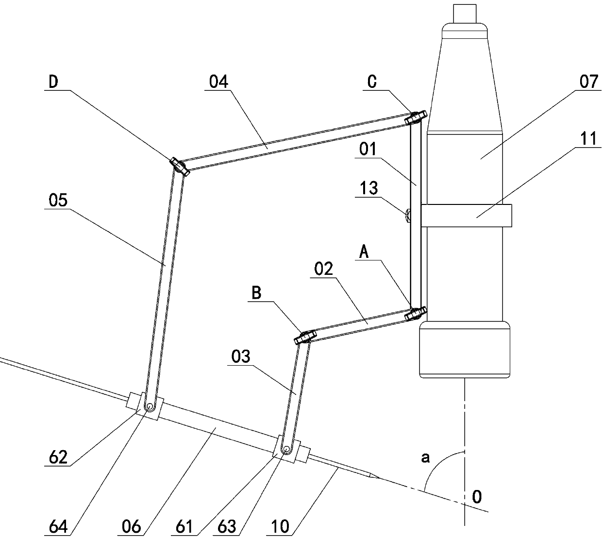
[0052] Embodiment 2: On the basis of Embodiment 1, the lower main swing rod, the lower slave swing rod, the upper master swing rod and the upper slave swing rod respectively include the left and right side rods and are fixed as a whole by the connecting rod in the middle, adjacent to each other. When the swing bar is connected with the corresponding lock bar and the lock nut, the shaft holes are arranged at the ends of the two side bars and the lock nut support sleeves are added between the shaft holes of the two side bars. The purpose of this design is to maintain moderate elasticity at the end of each swing rod. After the lock nut support sleeve is added, the lock nut support sleeve forms a locking structure with the corresponding lock rod and lock nut, which is more secure. From figure 1 and figure 2 It can be seen that no matter the guide sleeve in the adjustment device is adjusted to any angle and height, there are always two support points for constraining the guide sl...

Embodiment 3

[0053] Embodiment 3: On the basis of Embodiment 1, further, the lower fixed sleeve and the upper fixed sleeve fitted outside the guide sleeve can slide along the guide sleeve and be locked and fixed. This method can adjust the lower fixed sleeve and the upper fixed sleeve respectively, which essentially expands the swing angle range of the guide sleeve.

Embodiment 4

[0054] Embodiment 4: On the basis of Embodiment 1, compared with the fixing seat fixed on one side of the installation collar in Embodiment 1, this embodiment adopts the radial arrangement of fixed wires at the symmetrical positions on both sides of the installation collar respectively, And the symmetrical fixing wires on both sides pass through the center of the installation collar, such as Figure 9 and Figure 10 As shown, the two sides of the fixing seat are respectively connected with the corresponding fixing wires, so that the fixing seat is fixed on the symmetrical positions of the two sides of the installation collar over the diameter.


PUM


Abstract

The invention discloses an abdominocentesis needle guiding and directing device which comprises a fixed seat and a mounting ferrule connected with the fixed seat and used for being provided with a B-mode ultrasound probe. The lower end and the upper end of the fixed seat are connected with a lower swing rod set and an upper swing rod set respectively, and a guide sleeve component is mounted at thetail end of each swing rod set. There are always two supporting points for constraining a guide sleeve no matter at which angle and height the guide sleeve is adjusted, and stability of the guide sleeve can be improved by means of utilizing the supporting points to fix the guide sleeve from two ends. A laser device can be mounted at a position where a lower-portion main swing rod and a lower-portion auxiliary swing rod are hinged, and swing amplitude of the laser device is half that of the guide sleeve, so that a projection extension line of the laser device passes the tail end of a puncturepoint positioned in an abdominal cavity.

Description

technical field [0001] The invention belongs to the technical field of puncture needle auxiliary equipment for organ tissue sampling and injection treatment in clinical medicine, and in particular relates to a puncture needle guiding orienting device for abdominal puncture. Background technique [0002] Paracentesis needs to insert the puncture needle directly from the anterior abdominal wall into the peritoneal cavity, which has dual functions of diagnosis and treatment, and is one of the commonly used operating techniques in clinical medicine. The clinical application of paracentesis is relatively common, and it is suitable for patients with suspected abdominal organ damage after abdominal trauma; patients with peritoneal irritation symptoms but unknown reasons suspected of perforation of the consumption tract and peritoneal hemorrhage; patients with ascites of unknown etiology; When the pain is obvious, put ascites appropriately to relieve symptoms; intraperitoneal drug t...

Claims


Application Information

Patent Timeline
Patent Type & Authority Applications(China)
IPC IPC(8): A61B17/34
CPCA61B17/3403A61B17/3462A61B2017/3413
Inventor 张铁山尚曙玉王聪颖邢汝月王冬梅陈喆
Owner HUANGHE S & T COLLEGE
Learn More