Laser Scanning Train Loading Detection Device

A technology of laser scanning and detection device, applied in the direction of measurement device, optical device, collaborative operation device, etc., can solve the problems of overloaded carriage, high labor intensity of staff, low loading efficiency, etc., to reduce the no-load rate, The effect of improving continuous operation intensity and transportation efficiency and improving efficiency

Active Publication Date: 2021-02-09
CCCC MECHANICAL & ELECTRICAL ENG
View PDF11 Cites 0 Cited by
  • Summary
  • Abstract
  • Description
  • Claims
  • Application Information

AI Technical Summary

Problems solved by technology

In the above process, after the train arrives at the coal loading point, the coal can be put into the conveyor belt conveyor and transported to the compartment through the coal feeder. The degree of automation has improved, but the weighing method in the loading process is usually not quantitative, and also No measurement, until the carriages are full, and after arriving at the terminal port of the freight, the rail scale weighing method is adopted. This method cannot be loaded in advance, and it is easy to overload the carriages or lose tons. The degree of automation is generally low, mainly based on manual control. The staff need to check and supervise the loading process in real time. Not only the labor intensity of the staff is high, but also the loading efficiency is low, and it is easy to cause insufficient or excessive loading of the train

Method used


Image

  • Laser Scanning Train Loading Detection Device

Examples


Embodiment Construction

[0032] The present invention will be further described in detail below in conjunction with the accompanying drawings, so that those skilled in the art can implement it with reference to the description.

[0033] It should be noted that in the description of the present invention, the orientation or positional relationship indicated by the term is based on the orientation or positional relationship shown in the drawings, which is only for the convenience of describing the present invention and simplifying the description, and does not indicate or imply No device or element must have a specific orientation, be constructed, and operate in a specific orientation and therefore should not be construed as limiting the invention.

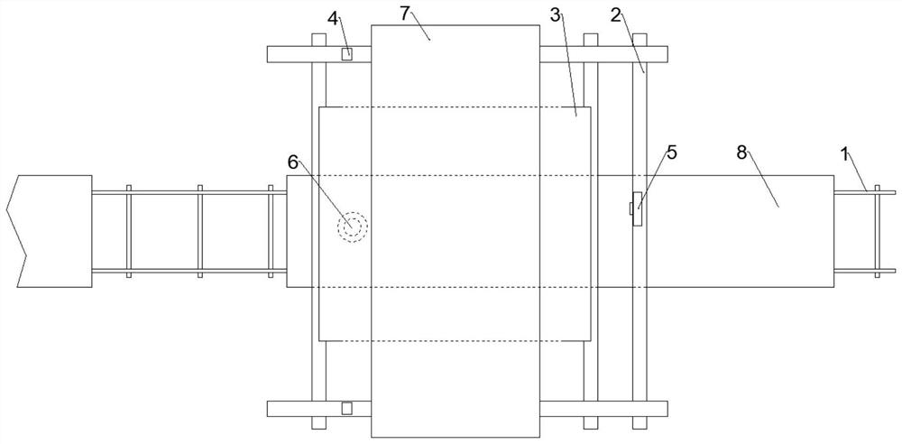
[0034] Such as figure 1 As shown, the present invention provides a laser scanning type train loading detection device, comprising:

[0035] The bracket system 2 is erected on both sides of the track 1; it is used to support various components of the train ...


PUM


Abstract

The invention discloses a laser scanning type train loading detection device, which comprises: a bracket system, which is erected on both sides of the track; a main buffer bin, whose top is open, and a first discharge pipe is arranged at the bottom; a scraping mechanism; a first The laser scanner detects the distance from the carriage head to the detection point with a preset frequency; the second laser scanner detects the distance from the top surface of the material in the main buffer bin to the detection point with a preset frequency; the control center platform is used for Receive data and calculate the moving speed of the car. If the moving speed is within the speed threshold and the distance from the head of the car to the detection point is within the first distance threshold, the second laser scanner is triggered and the first electric valve is opened. When the second When the difference between the distance detected when the second laser scanner is started and the distance currently detected by the second laser scanner is within the second distance threshold, the first electric valve and the second laser scanner are closed. The invention has the beneficial effect of precisely controlling the loading volume of the compartment.

Description

technical field [0001] The invention relates to the field of train loading equipment. More specifically, the present invention relates to a laser scanning type train loading detection device. Background technique [0002] Although the current degree of automation of coal mining operations has improved, the raw coal after mining in the coal mine will first be sent to the raw coal bunker of the coal preparation plant, where the raw coal will be cleaned and processed into different coal products, and then the coal products will be sent to the product bin. Finally, the coal products Loading is carried out in the fire loading station as required, and finally the coal products are transported out by train. In the above process, after the train arrives at the coal loading point, the coal can be put into the conveyor belt conveyor and transported to the compartment through the coal feeder. The degree of automation has improved, but the weighing method in the loading process is usua...

Claims


Application Information

Patent Timeline
Patent Type & Authority Patents(China)
IPC IPC(8): G01B11/00G01B11/14B65G67/06G06K17/00
CPCB65G67/06G01B11/00G01B11/14G06K17/0022
Inventor 吕崇晓尹艳艳
Owner CCCC MECHANICAL & ELECTRICAL ENG
Why Eureka
Try Eureka