Rotor component of brushless motor

A brushless motor and rotor technology, applied in the direction of magnetic circuit rotating parts, magnetic circuit shape/style/structure, etc., can solve the problems of magnetic steel displacement, turbulent use environment, unstable fixation, etc. Reduced magnetic field fluctuation, fixed and stable effect

Pending Publication Date: 2020-02-21
JIANGSU LANGXIN ELECTRIC
View PDF0 Cites 0 Cited by
  • Summary
  • Abstract
  • Description
  • Claims
  • Application Information

AI Technical Summary

Problems solved by technology

[0002] The rotor assembly of the current motor includes a rotor core, a rear baffle and a rotor shaft. There are magnetic steels placed in the slots, and the magnetic steels are fixed in the form of clamping. The specific fixing method is: several U-shaped metal clamps are clamped on the rotor core. The rotor core is made of several specifications of silicon steel sheets. The placement slots on the outer circumference of the rotor core are surrounded by a number of similar triangular blocks arranged at intervals, and the metal clips are stuck on the triangular blocks, so that there is a metal clip in each placement slot One side of the rotor assembly, so that when the magnetic steel is stuck in the slot, it will contact with one side of the metal clip, and finally the slot will be locked in the slot. However, this rotor assembly has a relatively big disadvantage: the magnetic steel is stuck in the slot. Placed in the slot, it is only fixed by the tension force of the metal clip, and the fixation is not firm. The magnetic steel may be displaced in the axial and radial directions, which will cause fluctuations in the magnetic field, especially for the cooling fan drive motor used in the car. If the environment is bumpy, this shortcoming will be magnified, and the magnetic field fluctuation will be more obvious

Method used


Image

  • Rotor component of brushless motor
  • Rotor component of brushless motor
  • Rotor component of brushless motor

Examples


Embodiment Construction

[0026] The present invention will be described in further detail below through specific examples.

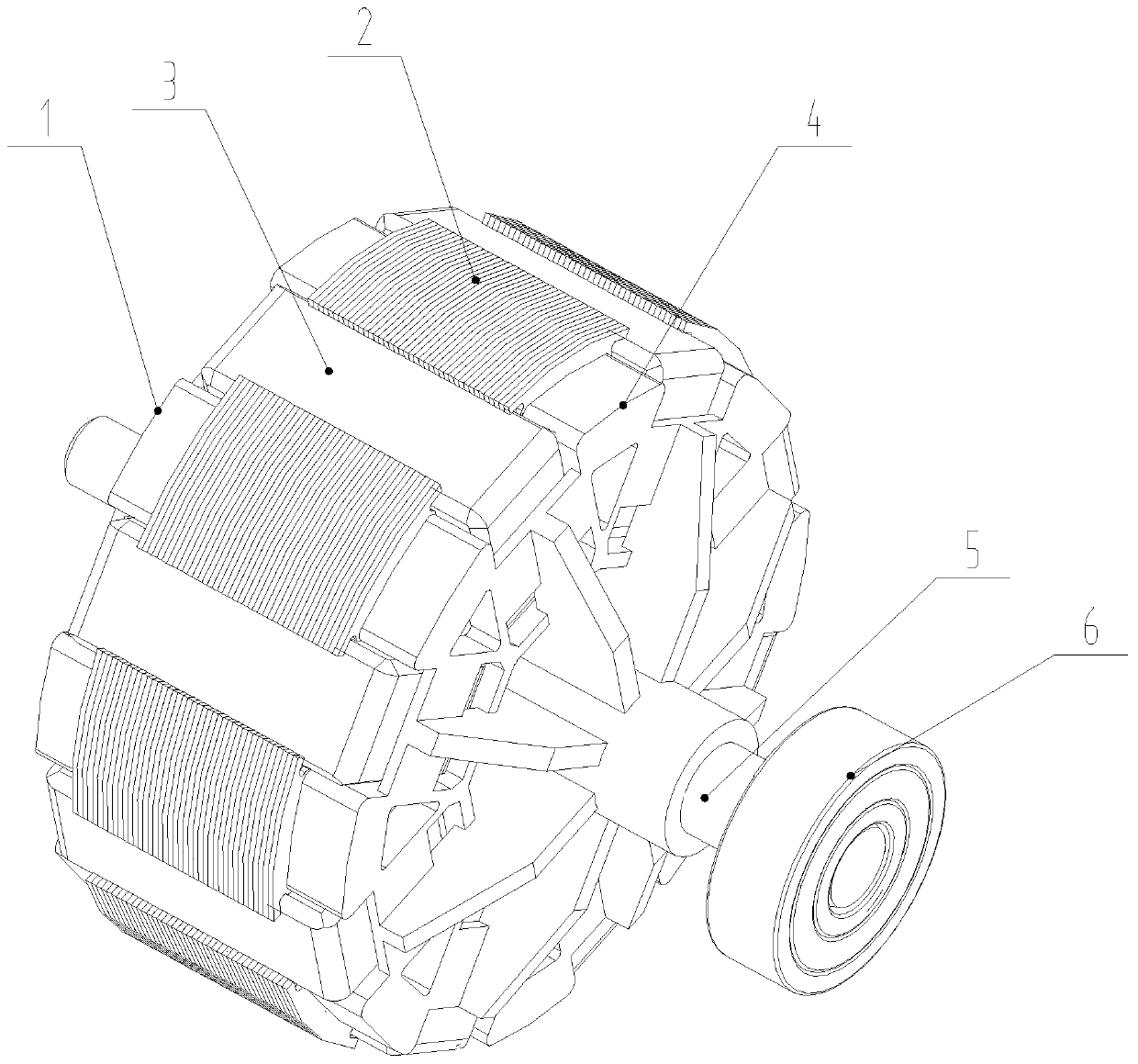
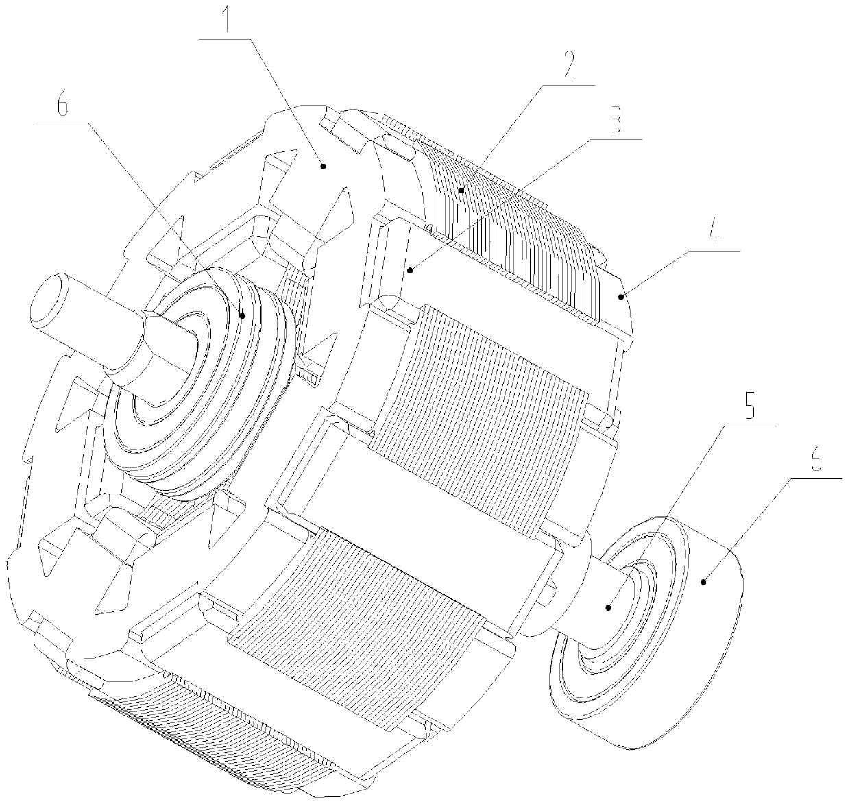
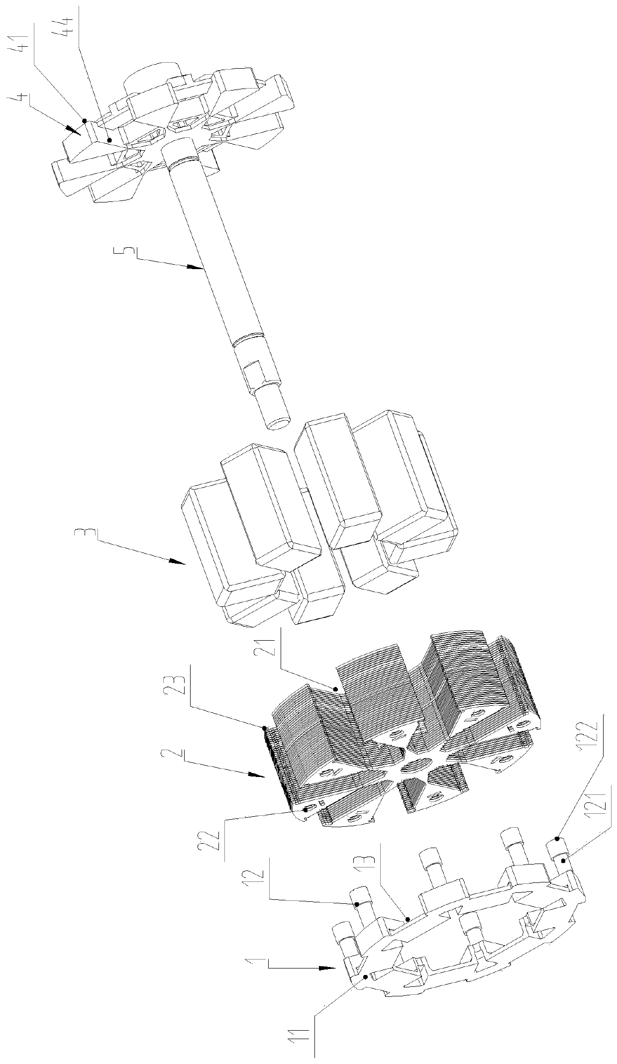
[0027] Such as Figure 1 to Figure 6 As shown, a rotor assembly of a brushless motor includes a rotor core 2, a rotor shaft 5, and a magnetic steel 3. The center of the rotor core 2 is provided with a central hole 25, and the outer circumference of the rotor core 2 is uniformly distributed. In the placement groove 21 where the magnetic steel 3 is placed, the rotor core 2 is formed by stacking silicon steel sheets of several specifications.

[0028] The rotor assembly also includes a front baffle 1 and a rear baffle 4, the rotor shaft 5 passes through the central hole 25 and the rear baffle 4 and is fixedly connected with the rear baffle, the front end and the rear end of the rotor shaft 5 are both arranged The bearing 6 is provided to facilitate the rotation of the whole rotor assembly and be installed on the casing of the motor.

[0029] The front baffle 1 is fixed on the fro...


PUM


Abstract

The invention discloses a rotor component of a brushless motor. The rotor component comprises a rotor core, a rotor shaft and magnetic steel. The center of the rotor core is provided with a central hole, placing grooves used for placing the magnetic steel are uniformly distributed on the periphery of the rotor core, the rotor assembly also comprises a front baffle plate and a rear baffle plate, the rotor shaft penetrates the central hole and the rear baffle plate and is fixedly connected with the rear baffle plate, the front baffle plate is fixed on the front end surface of the rotor core, therear baffle plate leans against the rear end surface of the rotor core, the magnetic steel is installed in the placing grooves and is restrained between the front baffle plate and the rear baffle plate in the front-back direction, and a radial limiting structure is arranged in each placing groove of the rotor core. The axial position and the radial position of the magnetic steel of the rotor component are restrained, so that the movement of the magnetic steel is reduced, and the magnetic field fluctuation is reduced.

Description

technical field [0001] The invention relates to a rotor assembly, in particular to a rotor assembly of a brushless motor. Background technique [0002] The rotor assembly of the current motor includes a rotor core, a rear baffle and a rotor shaft. There are magnetic steels placed in the slots, and the magnetic steels are fixed in the form of clamping. The specific fixing method is: several U-shaped metal clamps are clamped on the rotor core. The rotor core is made of several specifications of silicon steel sheets. The placement slots on the outer circumference of the rotor core are surrounded by a number of similar triangular blocks arranged at intervals, and the metal clips are stuck on the triangular blocks, so that there is a metal clip in each placement slot One side of the rotor assembly, so that when the magnetic steel is stuck in the slot, it will contact with one side of the metal clip, and finally the slot will be locked in the slot. However, this rotor assembly ha...

Claims


Application Information

Patent Timeline
Patent Type & Authority Applications(China)
IPC IPC(8): H02K1/28H02K1/27
CPCH02K1/27H02K1/28
Inventor 丁言闯朱磊陈志强
Owner JIANGSU LANGXIN ELECTRIC
Why Eureka
Try Eureka