Valve lift adjustment device

A technology for regulating devices and valve lifts, which is applied to valve devices, engine components, machines/engines, etc., and can solve problems such as load application

Inactive Publication Date: 2016-03-16
DENSO CORP
View PDF6 Cites 0 Cited by
  • Summary
  • Abstract
  • Description
  • Claims
  • Application Information

AI Technical Summary

Problems solved by technology

However, if the operation start time of the restriction pin is advanced, in the case where the restriction pin is inserted into the first half-perimeter portion of the groove, for example, the restriction pin may engage with the second half-perimeter portion of the groove, and the excessively large load thus may be applied to the limiting pin

Method used


Image

  • Valve lift adjustment device
  • Valve lift adjustment device
  • Valve lift adjustment device

Examples


Embodiment Construction

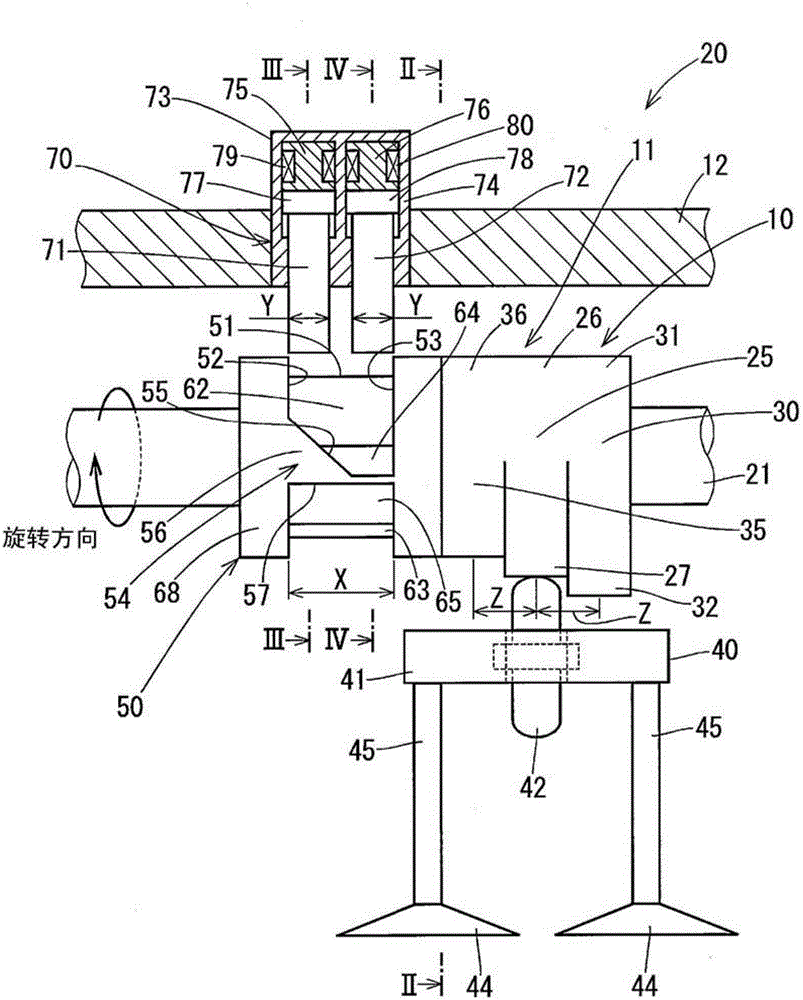
[0026] Embodiments will be described below with reference to the accompanying drawings. The valve lift adjusting device according to the embodiment is a cam-switching type variable valve mechanism, and in such as figure 1 used in the valve system shown. The valve system 20 is a system for opening or closing an intake valve 44 of an internal combustion engine.

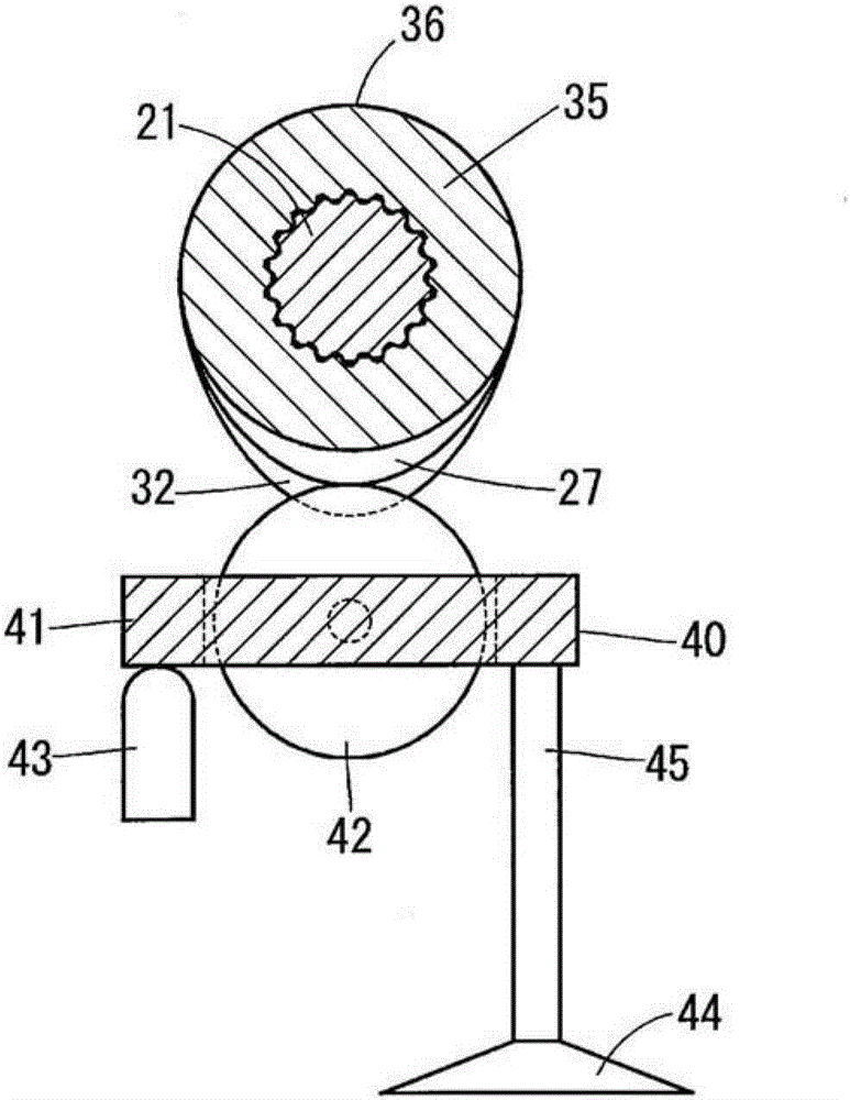
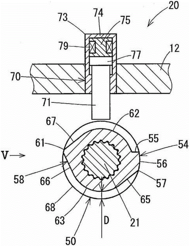
[0027] Such as Figures 1 to 5 As shown, the valve system 20 includes a camshaft 21, a low rotation cam 25, a high rotation cam 30, a low load cam 35, a roller lock 40, a lash adjustment device 43, an intake valve 44, a sliding device 50, and an actuating device. 70.

[0028] The low rotation cam 25 , the high rotation cam 30 , the sliding device 50 , and the actuating device 70 constitute the first valve lift adjustment device 10 . In the first valve lift adjusting device 10, the low-rotation cam 25 may correspond to a "first plate cam", and the high-rotation cam 30 may correspond to a "second plate cam".

[0029]...


PUM


Abstract

The present invention relates to a valve lift adjusting device (10,11) which comprises the following components: a first board cam (25,35), a second board cam (30,25), a sliding device (50) which is provided with a jointing tank (51), restricting components (71,72), and a driving unit (73). The axial width (X) of tank is equal with or larger than the summation of the length (Y) of the ends of the restricting components in the axial direction and the sliding amount (Z) of the sliding device. A wall (52) comprises a first projection (54) which further projects to the other wall (53) at back side in the rotation direction of the sliding device and displaces the sliding device to a second operation position when the first projection is jointed with the restricting component in rotation of the sliding device. The other wall comprises a second projection (58) which further projects to the former wall in the circumferential direction of the sliding device at a position different from the first projection at the back side in the rotation direction, and furthermore displaces the sliding device to the first operation position when the second projection is jointed with the restricting components in rotation of the sliding device.

Description

technical field [0001] The present disclosure relates to a valve lift adjustment device. Background technique [0002] A known valve lift adjusting device includes two types of plate cams capable of converting the rotational motion of a camshaft of an internal combustion engine into linear reciprocating motions of engine valves and adjusts the valve lift of the engine valves by switching between the plate cams. In the valve lift adjustment device described in US2011 / 0247577A1, two kinds of plate cams are fitted to the camshaft so as to be able to transmit rotation and to be able to be axially relatively displaced. The plate cams are located adjacently in the axial direction and are integrally formed with each other. The switching of the plate cam is carried out by a sliding device. [0003] The slider is a cylindrical member displaced integrally with the plate cam in the axial direction. The slide includes a wound groove on its radially outer wall, and the axial position ...

Claims


Application Information

Patent Timeline
Patent Type & Authority Patents(China)
IPC IPC(8): F01L13/00
CPCF01L1/047F01L1/267F01L13/0036F01L2013/0052F01L2013/101F01L2305/00F01L13/00
Inventor 天野均
Owner DENSO CORP
Why Eureka
Try Eureka