
A fully automatic terminal crimping device for easy cable positioning

A terminal crimping, fully automated technology, used in connections, circuit/collector parts, electrical components, etc., can solve the problems of poor crimping quality and effect, poor cable positioning accuracy, and low degree of automation. Improve crimping efficiency and automation, service life safety and reliability, and improve the effect of crimping quality

Active Publication Date: 2021-03-05
STATE GRID ZHEJIANG JIASHAN POWER SUPPLY CO LTD +1
View PDF3 Cites 1 Cited by
  • Summary
  • Abstract
  • Description
  • Claims
  • Application Information

AI Technical Summary

Problems solved by technology

[0003] The purpose of the present invention is to solve the problem that each step of the pressing method of the cable crimping device is independent and incoherent, the positioning accuracy of the cable is poor, the degree of automation is low, the product defect rate is high, the crimping quality and effect are not good, the pressing efficiency is low, and the labor cost is high. In order to solve the problem, a fully automatic terminal crimping device for cable positioning is proposed. The device has a simple structure, convenient use and installation, simple operation, accurate cable positioning, high degree of automation, compact layout, and good crimping efficiency and effect. , suitable for large, medium and small cable production enterprises. At the same time, it applies terminal crimping of various types of cable products, reduces operating costs, and has a long service life. It is a cable terminal crimping device with good safety and reliability.

Method used


Image

  • A fully automatic terminal crimping device for easy cable positioning
  • A fully automatic terminal crimping device for easy cable positioning
  • A fully automatic terminal crimping device for easy cable positioning

Examples


Embodiment Construction

[0024] The present invention will be further described below in conjunction with accompanying drawing:

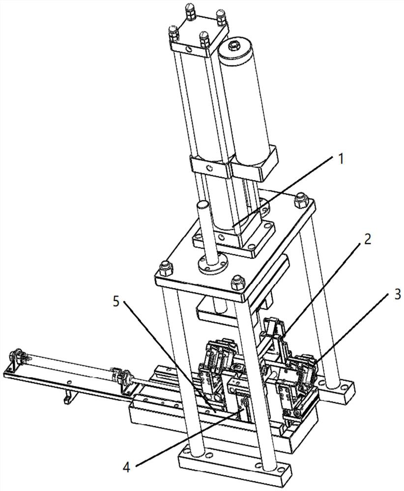
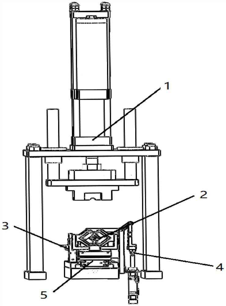
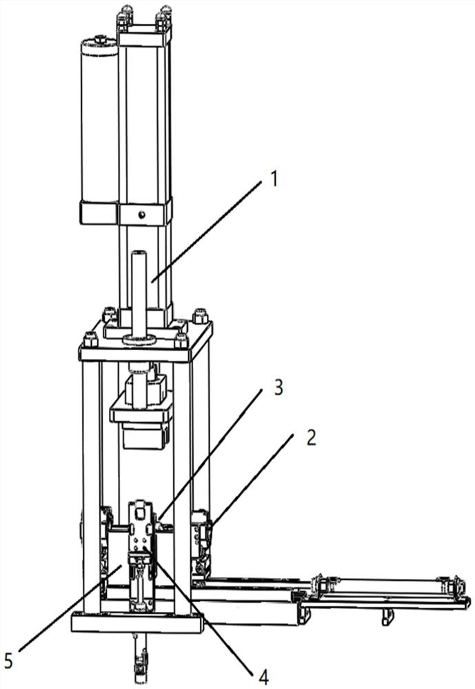
[0025] Such as Figure 1~8 As shown in the figure, a fully automatic terminal crimping device for easy cable positioning includes an upper die crimping mechanism 1, a cable positioning mechanism 3, an ejecting mechanism 4, a terminal pushing slider mechanism 5 and a terminal clamping mechanism 2. The terminal pushing slider mechanism 5 is arranged directly below the upper die crimping mechanism 1, the terminal pushing slider mechanism 5 is provided with a lower die base 44 for placing the processed cable terminals 45, and the terminal clamping mechanism 2 and the ejection mechanism 4 are respectively arranged on the left and right sides of the lower die base 44, and the front and rear ends of the lower die base 44 are respectively provided with a cable positioning mechanism 3 for clamping and positioning the cables.

[0026] The upper die crimping mechanism 1 includes a fi...


PUM


Abstract

The invention discloses a fully automated terminal crimping device that facilitates cable positioning, including an upper die crimping mechanism, a cable positioning mechanism, an ejection mechanism, a terminal pushing slider mechanism and a terminal clamping mechanism. The terminal pushing slider mechanism It is arranged directly below the upper die crimping mechanism. The terminal pushing slider mechanism is provided with a lower die base. The terminal clamping mechanism and the ejection mechanism are respectively arranged on the left and right sides of the lower die base. The lower die base A cable positioning mechanism is provided at the front and rear ends respectively; the present invention uses multiple mechanisms to cooperate with each other in a coordinated and orderly manner to complete the crimping function, improve the crimping efficiency and automation level, and uses the clamping claw assembly in the cable positioning mechanism to complete the wire connection. The cable positioning is accurate, and the terminal clamping mechanism is used to improve the terminal crimping quality. It has a simple structure, is easy to use, has a long service life, is safe and reliable, and is suitable for large, medium and small cable production companies. It can also apply terminals for many types of cable products. Crimp.

Description

technical field [0001] The present invention relates to the field of cable assembly equipment manufacturing, and more specifically, to a fully automatic terminal crimping device that facilitates cable positioning. Background technique [0002] Cable terminal is a kind of wire, power cable and electrical equipment used to connect power distribution devices in the electrical industry, household appliances and other industries. It is an accessory product to realize electrical connection. In the authorized notification number CN 205488953 U utility model patent, the cable crimping terminal can only complete simple crimping work, there is no exact positioning device, and it cannot reach the degree of automation. In the authorized announcement number CN 208093925 U utility model patent, the cable crimping terminal is positioned at the incoming line, there is no two-way positioning device for positioning, the crimping process is only crimped once, and the crimping quality is not hi...

Claims


Application Information

Patent Timeline
Patent Type & Authority Patents(China)
IPC IPC(8): H01R43/048H01R43/052
CPCH01R43/048H01R43/052H01R43/055
Inventor 徐勇明李飞伟姚建华苏毅方俞涛张冲标于敏英陆勇健潘峰舟李运钱王帅戴元安王欣唐军
Owner STATE GRID ZHEJIANG JIASHAN POWER SUPPLY CO LTD
Learn More