Pre-pressing and crimping machine

A crimping machine and pre-pressing technology, applied in the field of automation, can solve the problems of kneeling pins, defective products, and high precision requirements for connectors

Pending Publication Date: 2020-01-10
SHENZHEN XING GRAIN AUTOMATION CO LTD
View PDF0 Cites 1 Cited by
  • Summary
  • Abstract
  • Description
  • Claims
  • Application Information

AI Technical Summary

Problems solved by technology

[0002] The connector is a very common electronic component, which is often used to be inserted on the PCB board. The bottom of the connector is equipped with double-row side-by-side metal pins, and the metal pins are inserted into the correspondingly designed pin holes on the PCB board. , to achieve electrical conduction; the assembly of connectors is a production work with high precision requirements and difficult processes; at present, the following technical difficulties need to be overcome in the connector assembly process: 1. The crimping head is specially designed for the connector, and the connector is pressed into the pinhole of the PCB board through the crimping head. During the crimping process, since the crimping head and the connector pins are in surface contact, when the planes of the two are not parallel The position where the connector first contacts the pin is pressed deeper than the position where the second contact pin is. In this case, the pin kneeling is very likely to occur, resulting in crimping failure and defective products; 2. Different connectors require different crimping heads for crimping , in order to improve the versatility of the equipment, it is necessary to design a convenient clamping, simple replacement of the indenter and the indenter replacement mechanism; 3. The problem of automatic storage and automatic feeding of the connector

Method used


Image

  • Pre-pressing and crimping machine
  • Pre-pressing and crimping machine
  • Pre-pressing and crimping machine

Examples


Embodiment Construction

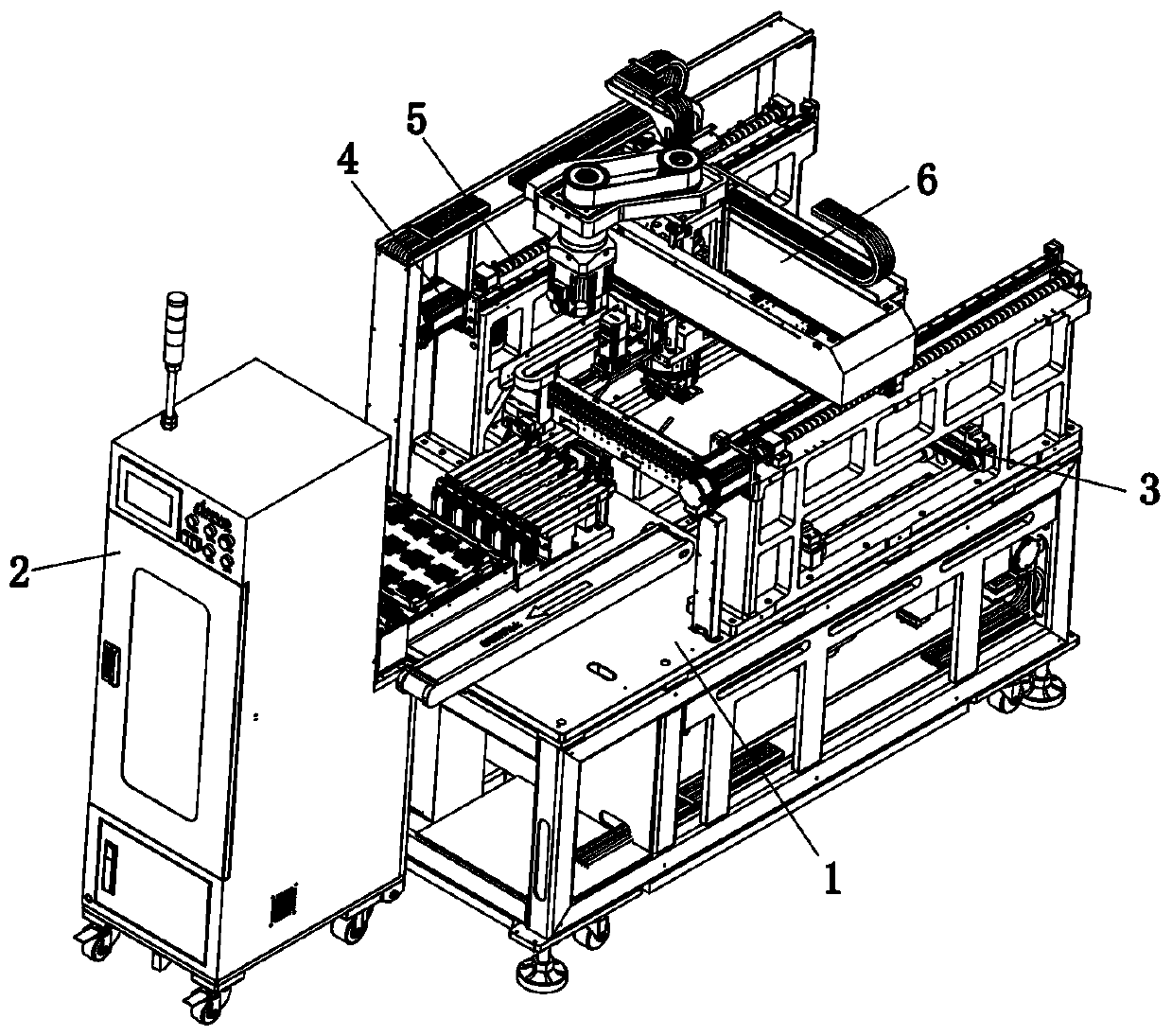
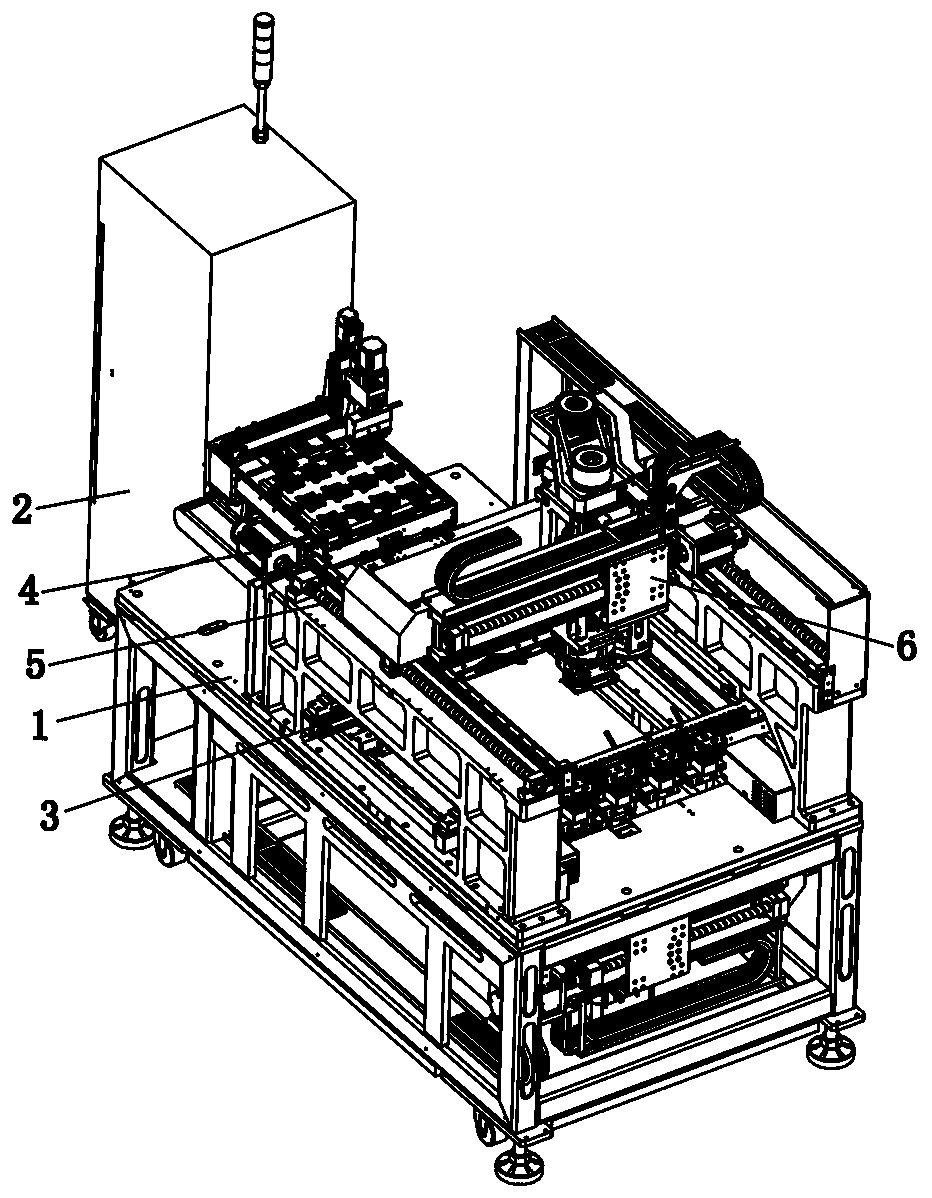
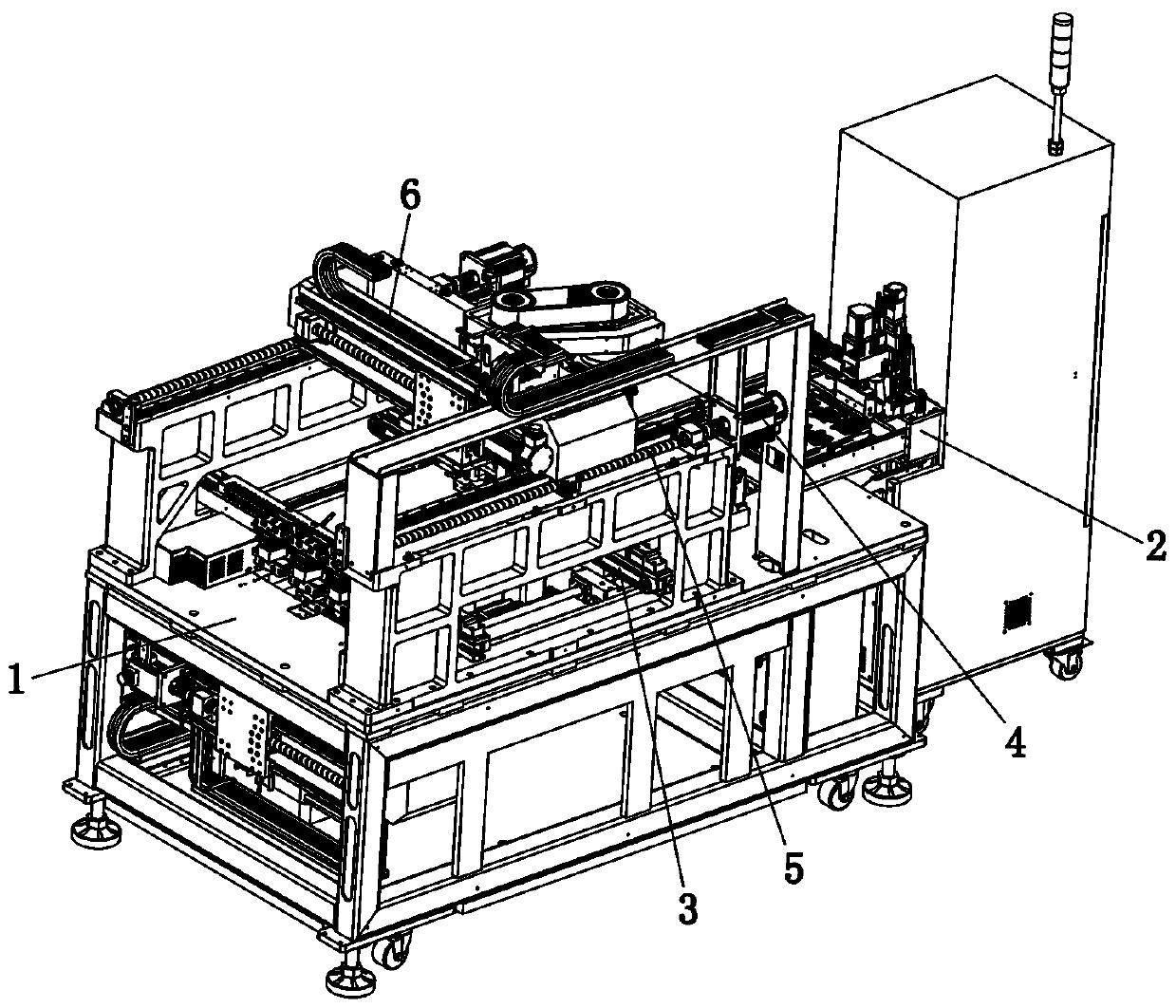
[0051] The present invention will be further described below in conjunction with accompanying drawing:

[0052] like Figure 1 to Figure 25 As shown, the technical scheme adopted by the present invention is as follows: a pre-pressing and crimping machine, including a frame 1 and a transmission mechanism 3 arranged on the frame 1, the two ends of the transmission mechanism 3 and the transmission of equipment located in the front and rear processes Mechanisms are connected, and a transmission space is formed between the transmission mechanisms. The PCB board to be processed is placed in the transmission space and transported straight forward, including the feeding mechanism 2, the upper pressing mechanism 6, the lower pressing mechanism 7 and the pressure head replacement seat 8 , wherein, the above-mentioned feeding mechanism 2 is arranged on one side of the frame 1, and the electronic components O to be assembled on the PCB board are stored in layers in the feeding mechanism 2...


PUM


Abstract

The invention discloses a pre-pressing and crimping machine which comprises a feeding mechanism, an upper pressing mechanism, a lower pressing mechanism and pressing head replacement bases. The feeding mechanism is arranged on one side of a frame. Electronic components to be assembled on a PCB are stored centrally in the feeding mechanism in a layered way. The upper pressing mechanism is arrangedacross the upper part of the transmission mechanism. The upper part and the lower part of the pressing base of the upper pressing mechanism are arranged at intervals and connected through a supportingsphere. The lower part of the pressing base is detachably connected with a first pressing head. The first press head is sucked upward by the pressing base and clamped and fixed from the two sides. The first pressing head pre-presses and/or crimps the electronic components inserted on the PCB from the upper part. The lower pressing mechanism is arranged below the transmission mechanism. There areat least two sets of pressing head replacement bases are arranged at the side part of the transmission mechanism. A large amount of automatic storage and automatic feeding of connectors can be realized, and the planes are automatically adapted and mutually bonded in parallel during crimping so that the condition of kneeling pins can be effectively reduced, the crimping quality can be improved, and the machine has the pressing head replacement function and high universality.

Description

technical field [0001] The invention relates to the field of automation, in particular to a pre-pressing and crimping machine. Background technique [0002] The connector is a very common electronic component, which is often used to be inserted on the PCB board. The bottom of the connector is equipped with double-row side-by-side metal pins, and the metal pins are inserted into the correspondingly designed pin holes on the PCB board. , to achieve electrical conduction; the assembly of connectors is a production work with high precision requirements and difficult processes; at present, the following technical difficulties need to be overcome in the connector assembly process: 1. The crimping head is specially designed for the connector, and the connector is pressed into the pinhole of the PCB board through the crimping head. During the crimping process, since the crimping head and the connector pins are in surface contact, when the planes of the two are not parallel The posi...

Claims


Application Information

Patent Timeline
Patent Type & Authority Applications(China)
IPC IPC(8): H01R43/20H01R43/24H01R43/048H01R43/055
CPCH01R43/0482H01R43/055H01R43/20H01R43/24
Inventor 宾兴李明星李太松
Owner SHENZHEN XING GRAIN AUTOMATION CO LTD
Why Eureka
Try Eureka