
A sliding installation device with compensation mechanism for remote sensing scanning mirror

A technology of compensation mechanism and installation device, which is applied in the field of remote sensing scanning mirrors, can solve problems such as difficulty in satisfying sliding and angle adjustment, difficulty in compensating satellite attitude deviation information, etc., and achieves the effects of facilitating scanning, reducing maintenance costs, and simple sliding structure

Active Publication Date: 2021-05-07
JILIN JIANZHU UNIVERSITY
View PDF6 Cites 0 Cited by
  • Summary
  • Abstract
  • Description
  • Claims
  • Application Information

AI Technical Summary

Problems solved by technology

As for satellite attitude deviation information, due to its high precision requirements, the installation structure of ordinary remote sensing scanning mirrors is generally only realized by using rotating parts and sliding parts. This method and structure are difficult to meet high-precision sliding and angle adjustment. It is difficult to realize the compensation of satellite attitude deviation information

Method used


Image

  • A sliding installation device with compensation mechanism for remote sensing scanning mirror
  • A sliding installation device with compensation mechanism for remote sensing scanning mirror
  • A sliding installation device with compensation mechanism for remote sensing scanning mirror

Examples


Embodiment Construction

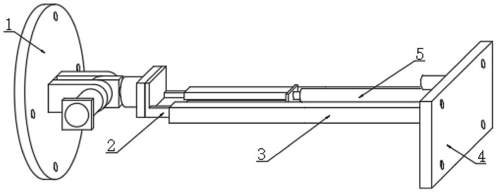
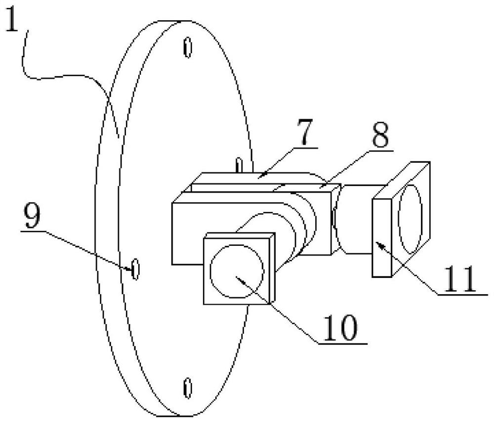
[0024] see Figure 1~5 , in an embodiment of the present invention, a sliding mounting device with a compensation mechanism for a remote sensing scanning mirror, including a remote sensing scanning mirror mounting head 1, a mounting positioning seat 4, a sliding telescopic mechanism, a first rotation mechanism and a second rotation mechanism , wherein one end of the sliding telescopic mechanism is installed on the installation positioning seat, the other end of the sliding telescopic mechanism is fixedly connected to the first rotating mechanism, and the first rotating mechanism is connected to the The remote sensing scanning mirror installation head 1 is characterized in that the first rotating mechanism and the second rotating mechanism are provided with an accuracy compensation component; The rotated angles of the first rotating mechanism and the second rotating mechanism are precisely compensated, and the range of the angle compensated by the precision compensating compone...


PUM


Abstract

The present invention relates to the technical field of remote sensing scanning mirrors, in particular to a sliding installation device with a compensation mechanism for remote sensing scanning mirrors. The present invention sets precision compensating components on both the first rotating mechanism and the second rotating mechanism. In this way, not only The rapid angle adjustment of the scanning mirror can be realized, and the high-precision compensation of the angle can be realized, and the precision compensation component of the present invention can control the first rotation mechanism and the second rotation mechanism according to the satellite attitude deviation information corresponding to the remote sensing scanning mirror. The angle after the rotation of the mechanism is precisely compensated, and the angle range compensated by the precision compensation component is -5° to +5°, ensuring image quality. The angle compensation driving mechanism of the present invention can realize high-precision control, and real-time detection feedback control , the shape and size of the compensation ring groove can be designed according to the required accuracy and other conditions, so as to realize the control required by different accuracy or angle compensation, and improve the accuracy of angle control during the sliding process.

Description

technical field [0001] The invention relates to the technical field of remote sensing scanning mirrors, in particular to a sliding mounting device with a compensation mechanism for remote sensing scanning mirrors. Background technique [0002] At present, for remote sensing scanning mirrors, when observing the earth with remote sensing satellites, the movement of the scanning mirrors has an important relationship and influence with the attitude information of the satellites, thus affecting the image quality. Therefore, when using the scanning mirror to scan, the satellite attitude deviation information needs to be taken into consideration. As for satellite attitude deviation information, due to its high precision requirements, the installation structure of ordinary remote sensing scanning mirrors is generally only realized by using rotating parts and sliding parts. This method and structure are difficult to meet high-precision sliding and angle adjustment. It is difficult t...

Claims


Application Information

Patent Timeline
Patent Type & Authority Patents(China)
IPC IPC(8): F16M11/04F16M11/12F16M11/18G01D5/26G02B26/10
CPCF16M11/043F16M11/121F16M11/18G01D5/26G02B26/10
Inventor 尹楠肖扬孙妍
Owner JILIN JIANZHU UNIVERSITY
Learn More