Gap bridging system

A gap and bridging technology, applied in the direction of vehicle components, pedals or ladders, railway car body components, etc., can solve problems such as pedal skew, drive device or control electronic device layout difficulties, etc., to achieve small force and realize structural space Gain, skew prevention effect

Active Publication Date: 2020-02-18
SIEMENS MOBILITY AUSTRIA GMBH
View PDF5 Cites 0 Cited by
  • Summary
  • Abstract
  • Description
  • Claims
  • Application Information

AI Technical Summary

Problems solved by technology

However, since these guide elements may have a greater installation space requirement here, they can be replaced by a larger number of guide elements each having a lower load-carrying capacity, but this makes the other components of the gap bridging system , e.g. the layout of the drive or control electronics becomes difficult
Likewise, care should be taken when designing the guide mechanism of the pedals to use either fixed bearings or floating bearings, respectively, at the appropriate positions, since otherwise manufacturing tolerances or twists of the carriage or of the housing of the gap bridging system can lead to skewing of the pedals

Method used


Image

  • Gap bridging system
  • Gap bridging system
  • Gap bridging system

Examples


Embodiment Construction

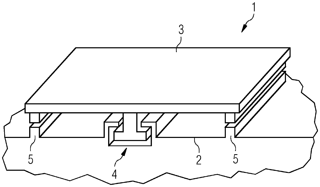
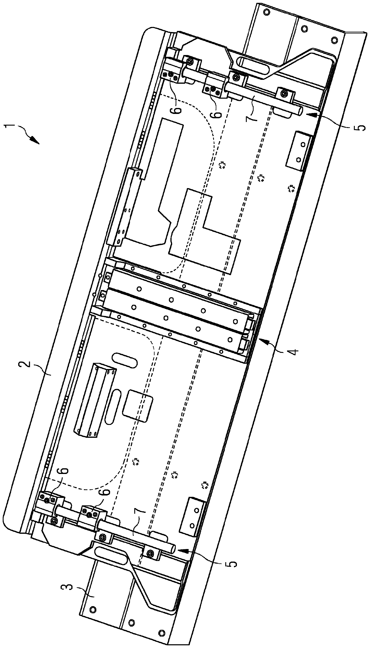
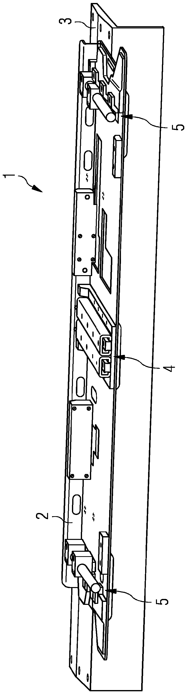
[0017] figure 1 The principle of a gap bridging system is shown exemplarily and schematically. Shown in a highly abstract view is a gap bridging system 1 comprising a linearly slidable supported pedal 3 . The pedal 3 is slidably supported by means of a sliding bearing consisting of two sliding bearing-linear guides 5 and a rolling bearing-linear guide 4 . The sliding bearing-linear guide 5 is designed here as a floating bearing and transmits the forces between the pedal and the component carrier 2 or the carriage only in the vertical direction, the rolling bearing-linear guide 4 then transmits the force between the pedal and the component carrier 2 or the carriage. The forces between the component brackets 2 are transmitted in all spatial directions except the extension direction of the pedal 3 . Apart from the running board 1 and the linear guides 4 , 5 , the gap bridging system 1 also includes a component carrier 2 , via which the gap bridging system 1 can be connected to ...


PUM


Abstract

The invention relates to a gap bridging system (1) for a rail vehicle, for bridging the gap between the floor of a passenger compartment and a station platform, comprising a component support (2) anda step plate (3) which is mounted with respect to the component carrier by a slide mounting such that it can slide, the slide mounting comprising a rolling bearing linear guide (4) and two sliding bearing linear guides (5).

Description

technical field [0001] The invention relates to a gap bridging system for a gap between a passenger compartment floor and a platform of a rail vehicle. Background technique [0002] Gap bridging systems are used in modern rail vehicles to enable a comfortable alighting and disembarking of passengers, especially persons with restricted mobility, and in particular to remove gaps caused by the gap between the passenger compartment floor and the platform Risks are reduced to a minimum. For typical rail vehicles (for example subways), such gaps have a width of approximately 100 mm, but for station platforms, for example, can also be as high as 300 mm at track bends. In order to bridge such platform gaps, sliding small platforms can be used which comprise slidingly supported plates which can slide out of the vehicle under force support. In this case, the smallest possible installation space requirement is desired, so that the gap bridging systems should be produced with the smal...

Claims


Application Information

Patent Timeline
Patent Type & Authority Applications(China)
IPC IPC(8): B61D23/02B60R3/02
CPCB61D23/00B61D23/025
Inventor M.克罗纳贝特F.埃德尔
Owner SIEMENS MOBILITY AUSTRIA GMBH
Why Eureka
Try Eureka