
Hot stamping machine capable of conveniently replacing hot stamping heads for plastic plate processing

A technology that facilitates the replacement of hot stamping heads. It is applied in printing machines, rotary printing machines, printing, etc. It can solve the problems of long-term use of devices, changes in spring tension, and instability of hot stamping heads, etc., to achieve stable movement and reduce installation costs. Effects of Difficulty and Ease of Distinction

Inactive Publication Date: 2020-02-18
湖州飞祥智能办公设备股份有限公司
View PDF0 Cites 0 Cited by
  • Summary
  • Abstract
  • Description
  • Claims
  • Application Information

AI Technical Summary

Problems solved by technology

[0005] The present invention provides a hot stamping machine for plastic plate processing that is convenient for replacing the hot stamping head, which can effectively solve the above-mentioned background technology, but the patent still has the following shortcomings. Although it can facilitate the replacement of the hot stamping head, this type method, the hot stamping head after replacement is unstable and prone to shaking, and after the spring is used for a long time, the tension of the spring will change, which will lead to the problem that the device cannot be used for a long time and needs regular maintenance

Method used


Image

  • Hot stamping machine capable of conveniently replacing hot stamping heads for plastic plate processing
  • Hot stamping machine capable of conveniently replacing hot stamping heads for plastic plate processing
  • Hot stamping machine capable of conveniently replacing hot stamping heads for plastic plate processing

Examples


Embodiment Construction

[0026] The preferred embodiments of the present invention will be described below in conjunction with the accompanying drawings. It should be understood that the preferred embodiments described here are only used to illustrate and explain the present invention, and are not intended to limit the present invention.

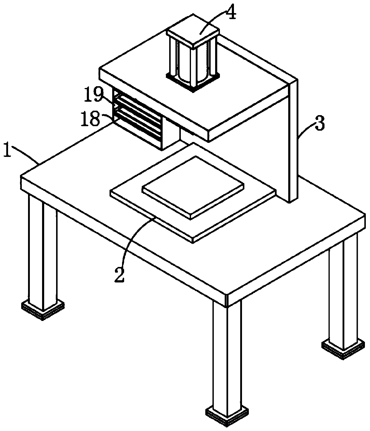
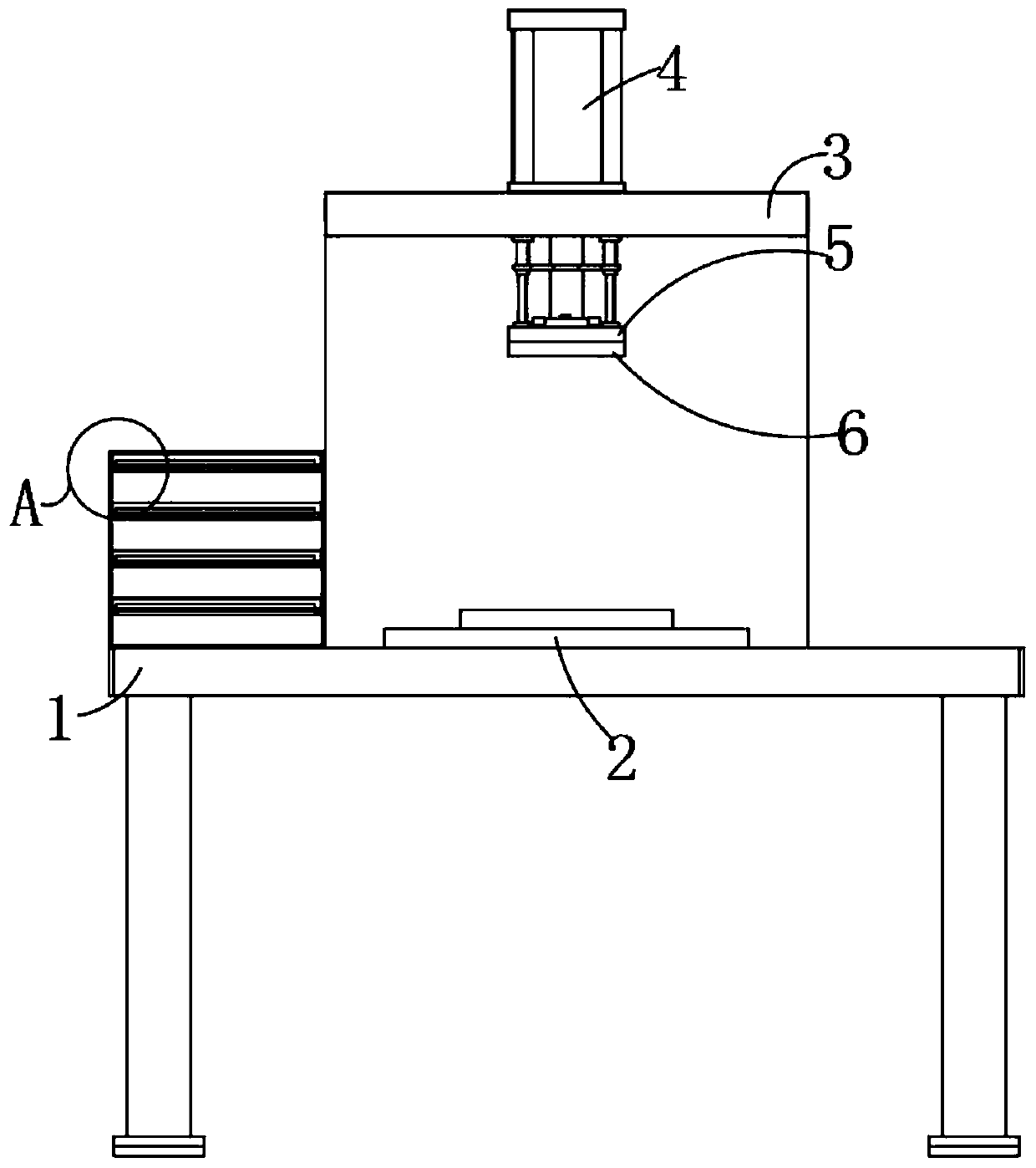
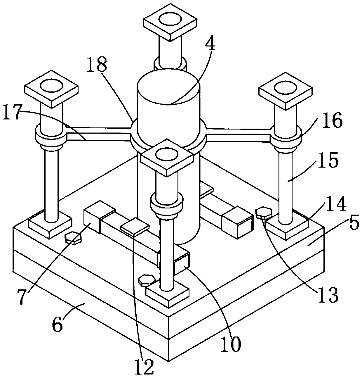
[0027] Example: such as Figure 1-6 As shown, the present invention provides a technical solution, a hot stamping machine for plastic plate processing that is convenient for replacing the hot stamping head, including a base plate 1, a working plate 2 is fixedly installed in the middle of the top of the base plate 1, and the four corners of the bottom end of the base plate 1 are fixed. Outriggers are connected, and the bottom edge of the outriggers is fixedly connected with a placement block, and the middle part of the bottom end of the placement block is connected with a shock-absorbing gasket, which can support the bottom plate 1, thereby increasing the supporting f...


PUM


Abstract

The invention discloses a hot stamping machine capable of conveniently replacing hot stamping heads for plastic plate processing. The hot stamping machine comprises a bottom plate, wherein the middleof the top end of the bottom plate is fixedly provided with a working plate, and an L-shaped plate is welded to the position, located at the edge of the back surface of the working plate, of the top end of the bottom plate; and an air cylinder is fixedly installed in the middle of the top end of the L-shaped plate, a connecting plate is fixedly installed in the middle of the bottom end of the aircylinder, the bottom end of the connecting plate is connected with a hot stamping plate, and the four corners of the top end of the hot stamping plate are each fixedly connected with a connecting block. By means of the connecting plate, the hot stamping plate, the connecting blocks, square holes, a positioning hole, a cross rod, a placing hole, a T-shaped block and fastening screws, the connectingblocks enter the connecting plate along the square holes, and then the cross rod is inserted into the positioning hole, so that the installation between the connecting plate and the hot stamping plate can be completed, and the installation difficulty between the connecting plate and the hot stamping plate is reduced. Meanwhile, the connecting plate and the hot stamping plate can be installed andfixed, so that the phenomenon of shaking after the connecting plate and the hot stamping plate are connected is prevented.

Description

technical field [0001] The invention relates to the technical field of plastic plate processing, in particular to a hot stamping machine for plastic plate processing which is convenient for replacing a hot stamping head. Background technique [0002] Plastic board is made of plastic. Plastic is a synthetic polymer compound that can change its shape freely. Plastic is a material that is polymerized by synthesis or condensation reaction using monomer raw materials. It is composed of synthetic resin and fillers, plasticizers, Composed of stabilizers, lubricants, colorants and other additives, the hot stamping machine can bake any color codes, portrait photos, landscape patterns, etc. on porcelain plates, porcelain plates, PVC plates, and metal plates, especially suitable for making medals, Power of attorney, advertising agency, exclusive shop sign, commemorative card, tombstone image, cultural shirt, etc.; [0003] For this reason, a Chinese patent discloses a hot stamping mac...

Claims


Application Information

Patent Timeline
Patent Type & Authority Applications(China)
IPC IPC(8): B41F19/06
CPCB41F19/068B41P2219/30B41P2219/40
Inventor 杨军坤
Owner 湖州飞祥智能办公设备股份有限公司
Learn More