Parking control method, parking server, vehicle controller and vehicle

A vehicle controller and control method technology, applied in the field of intelligent transportation, can solve the problems of slow speed, large error, unsuitable for precise parking of large trucks, etc., and achieve the effect of precise parking

Active Publication Date: 2020-02-14
BEIJING TUSEN ZHITU TECH CO LTD
View PDF5 Cites 7 Cited by
  • Summary
  • Abstract
  • Description
  • Claims
  • Application Information

AI Technical Summary

Problems solved by technology

[0003] At present, the most common vehicle parking methods are to locate vehicles and parking spaces through vehicle positioning equipment or vehicle cameras. This method has disadvantages such as large errors and slow speeds, and is especially not suitable for precise parking of large trucks.

Method used


Image

  • Parking control method, parking server, vehicle controller and vehicle
  • Parking control method, parking server, vehicle controller and vehicle
  • Parking control method, parking server, vehicle controller and vehicle

Examples


example 1

[0126] Such as Figure 4 As shown, there are 6 parallel lanes under the quay crane, the lane marks are E1~E6 respectively, the width of each lane is 3m, and each lane is drawn with a target parking line at a position 5m away from the quay crane (the oblique line in the figure As shown), Lidar and V2X transceiver equipment are installed in the middle of the quay bridge, and the scanning radius of the Lidar is 40m.

[0127] The area in the dotted line box is the scheduled monitoring area. The boundaries of the scheduled monitoring area in the vertical direction of the lane are the left side of the lane E1 and the right side of the lane E6. The boundaries of the scheduled monitoring area in the direction of the lane extension are the finish line and the start line, where the finish line is the straight line where the target stop line is located, 1m away from the shore crane, and the start line is a straight line 1m away from the finish line and parallel to the finish line.

[01...

example 2

[0137] Such as Figure 5 As shown, there are 6 parallel lanes under the quay crane. The signs of the lanes are E1~E6 respectively. The width of each lane is 6m. Each lane has a target parking line drawn at a position 5m away from the quay crane. The quay crane is equipped with Two laser radar Lidar1, Lidar2 and V2X transceiver devices, the scanning radius of the laser radar is 10m.

[0138] Lidar1 is responsible for scanning lanes E1-E3, and Lidar2 is responsible for scanning lanes E4-E6.

[0139] Lidar1 is responsible for scanning Figure 5 The predetermined monitoring area defined by the dotted box on the left side of the figure, the boundaries of the predetermined monitoring area in the vertical direction of the lane are respectively the left side of the lane E1 and the right side of the lane E3, and the boundaries of the predetermined monitoring area in the direction of the lane extension are respectively The finish line and the start line, where the finish line is the s...


PUM


Abstract

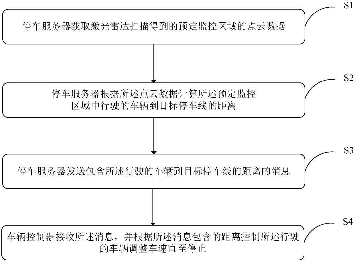
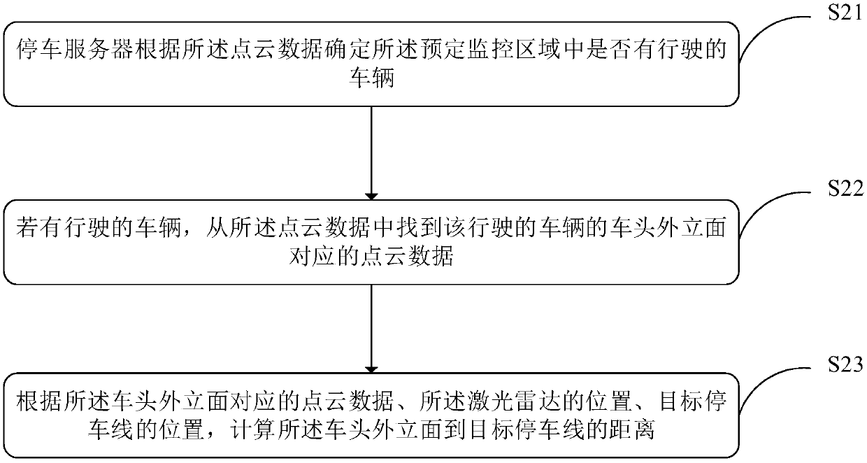
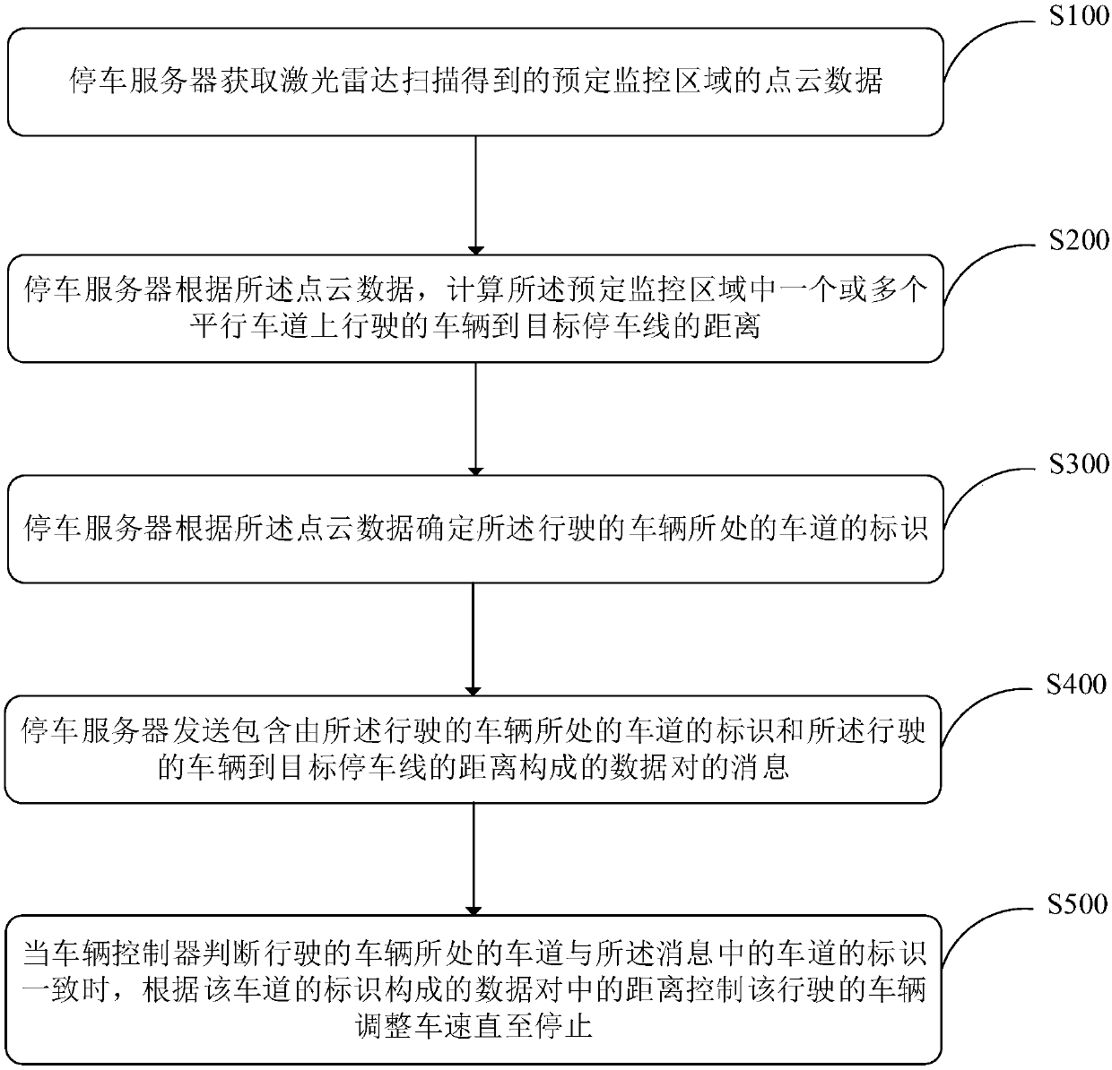
An embodiment of the present invention provides a parking control method, a parking server, a vehicle controller and a vehicle. The parking control method includes the following steps of obtaining point cloud data that are scanned by a laser radar and are located in a predetermined monitoring area by the parking server; calculating the distance from the vehicle traveling in the predetermined monitoring area to a target parking line according to the point cloud data by the parking server; sending a message containing the distance by the parking server; and using the vehicle controller to receive the message and controlling the vehicle to adjust the vehicle speed until stopping according to the distance. In the present invention, with the aid of the accurate ranging capability and fast processing speed of the laser radar, the vehicle can be controlled to decelerate step by step according to the distance from the vehicle to the target parking line, so as to realize the accuracy, stabilityand one-time accurate parking; and besides, the whole parking process is automatically completed instead of artificial command, and thus the method is suitable for the field of a remotely piloted vehicle.

Description

technical field [0001] Embodiments of the present invention relate to the technical field of intelligent transportation, and more specifically, embodiments of the present invention relate to a parking control method, a parking server, a vehicle controller, and a vehicle. Background technique [0002] This section is intended to provide a background or context for implementations of the invention that are recited in the claims. The descriptions herein are not admitted to be prior art by inclusion in this section. [0003] At present, the common vehicle parking methods are mostly to locate vehicles and parking spaces through vehicle-mounted positioning equipment or vehicle-mounted cameras. This method has disadvantages such as large errors and slow speeds, and is especially not suitable for precise parking of large trucks. [0004] The shore crane is the main loading and unloading equipment used between the container ship and the wharf. The loading and unloading efficiency of...

Claims


Application Information

Patent Timeline
Patent Type & Authority Applications(China)
IPC IPC(8): B60W30/06
CPCB60W30/06
Inventor 李海泉
Owner BEIJING TUSEN ZHITU TECH CO LTD
Why Eureka
Try Eureka