A contact piece anti-return connector

A technology of contacts and connectors, which is applied in the direction of vehicle connectors, connections, parts of connection devices, etc., can solve problems such as breakage, increased contact resistance of connectors, and prolapse of contacts, and achieves an effective and reliable anti-retraction method Effect

Active Publication Date: 2021-02-05
CHINA AVIATION OPTICAL-ELECTRICAL TECH CO LTD
View PDF6 Cites 0 Cited by
  • Summary
  • Abstract
  • Description
  • Claims
  • Application Information

AI Technical Summary

Problems solved by technology

[0003] At present, when many connector manufacturers design connectors, they only use one positioning method for the contacts, that is, use the claws on the contacts to clamp the contacts in the connector housing. This positioning structure uses the claws themselves Once the claw is overstressed, it will break, which will lead to the failure of the positioning structure, and then the contact will come out, and the contact resistance of the connector will increase, which will seriously lead to the ablation of the connector.

Method used


Image

  • A contact piece anti-return connector
  • A contact piece anti-return connector
  • A contact piece anti-return connector

Examples


Embodiment Construction

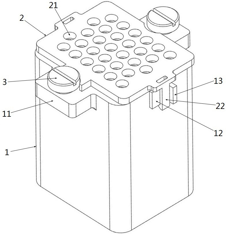
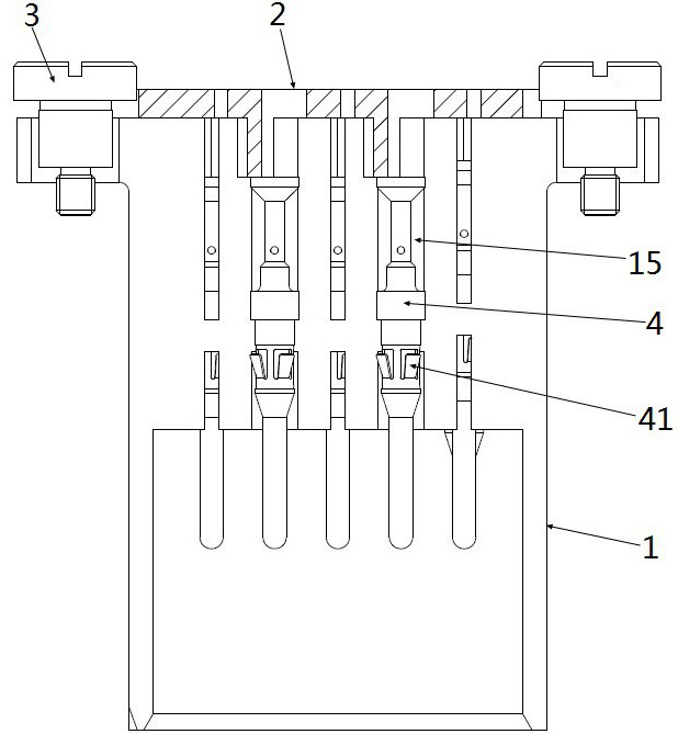
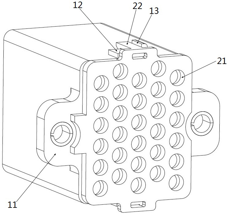
[0028] An embodiment of the anti-retraction connector of the contact piece in the present invention is as follows Figure 1~Figure 2 As shown, it includes a housing 1 and a baffle 2 connected to the housing 1, combined with Figure 5 As shown, the housing 1 is provided with a plurality of contact installation holes 15 , and the contacts 4 are installed in the contact installation holes 15 . The structure of the contact piece 4 is as figure 2 , Figure 6 as well as Figure 8 As shown, the front end of contact 4 ( Figure 8 The left end in the middle) is the plug end, the rear end ( Figure 8 The right end in the middle) is the wire outlet end, and the wire outlet end is provided with an outlet hole 42. In addition, the middle part of the contact piece 4 is provided with a claw 41, and a positioning stepped surface is provided in the mounting hole 15 of the contact piece to match the positioning of the claw 41. During the installation of the contact piece 4, the claw 41 is...


PUM


Abstract

The invention provides an anti-retraction connector for contacts, which comprises: a housing with a contact installation hole; a contact installed in the contact installation hole, the front end of the contact is a plug-in end, and the rear end is a The wire outlet end; the baffle, which is connected to the housing and is located on the rear side of the contact, and the baffle is provided with a stop structure for blocking and cooperating with the wire outlet end of the contact, so as to prevent the contact from exiting the housing backward , the baffle is also provided with wire holes for the wires on the contacts to pass through. The beneficial effect is that: since the housing is connected with a baffle, and the baffle is located at the rear side of the contact piece, the stop structure on the baffle cooperates with the wire outlet end of the contact piece, so that the contact piece can be prevented from exiting the housing backward. , which plays the role of anti-retraction, and a wire hole is set on the baffle to ensure that the wires on the contact can pass through smoothly. The invented anti-retreat method is more effective and reliable.

Description

technical field [0001] The invention relates to an anti-retraction connector of a contact piece. Background technique [0002] With the gradual development of electric vehicles, their safety has attracted more and more attention from consumers, and electric vehicle ablation problems are also common. There are various reasons for their ablation, including vehicle failures caused by connector ablation , There are also various reasons for connector ablation, among which the ejection of contacts is one of the more typical reasons. [0003] At present, when many connector manufacturers design connectors, they only use one positioning method for the contacts, that is, use the claws on the contacts to clamp the contacts in the connector housing. This positioning structure uses the claws themselves Once the claw is overstressed, it will break, which will lead to the failure of the positioning structure, and then the contact will come out, and the contact resistance of the connector...

Claims


Application Information

Patent Timeline
Patent Type & Authority Patents(China)
IPC IPC(8): H01R13/432H01R13/436
CPCH01R13/432H01R13/4367H01R2201/26
Inventor 李永棒
Owner CHINA AVIATION OPTICAL-ELECTRICAL TECH CO LTD
Why Eureka
Try Eureka