
A Steel Plate Concrete Shear Wall Convenient for Space Limitation

A steel plate concrete and shear wall technology, applied to walls, buildings, building components, etc., can solve problems such as inaccurate data, failure to obtain experimental data, and falling of shear walls, achieving high safety, accurate experimental data, The effect of quality improvement

Active Publication Date: 2021-08-31
CHINA MCC17 GRP
View PDF9 Cites 0 Cited by
  • Summary
  • Abstract
  • Description
  • Claims
  • Application Information

AI Technical Summary

Problems solved by technology

However, most of the test methods for the bearing capacity of steel plate concrete shear walls that are convenient to limit the position have the following problems: 1. The data are not accurate enough. Heavy objects are hung on the side to increase the pressure of the whole method. Since the quality of the heavy objects is fixed, accurate experimental data cannot be obtained; second, it is not stable enough. At present, most of the steel plate concrete shear walls are wrapped in the shear wall during the experiment. In one layer of wooden boards, and the fixing device is fixed on the wooden board by screws, when the entire wooden board is subjected to excessive load, it is prone to breakage, which leads to the risk of falling of the shear wall inside the wooden board

Method used


Image

  • A Steel Plate Concrete Shear Wall Convenient for Space Limitation
  • A Steel Plate Concrete Shear Wall Convenient for Space Limitation
  • A Steel Plate Concrete Shear Wall Convenient for Space Limitation

Examples


Embodiment 1

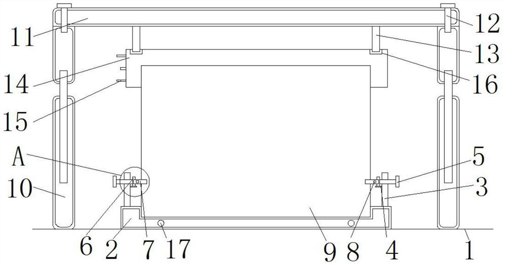
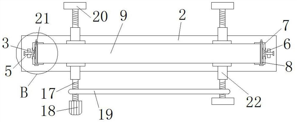
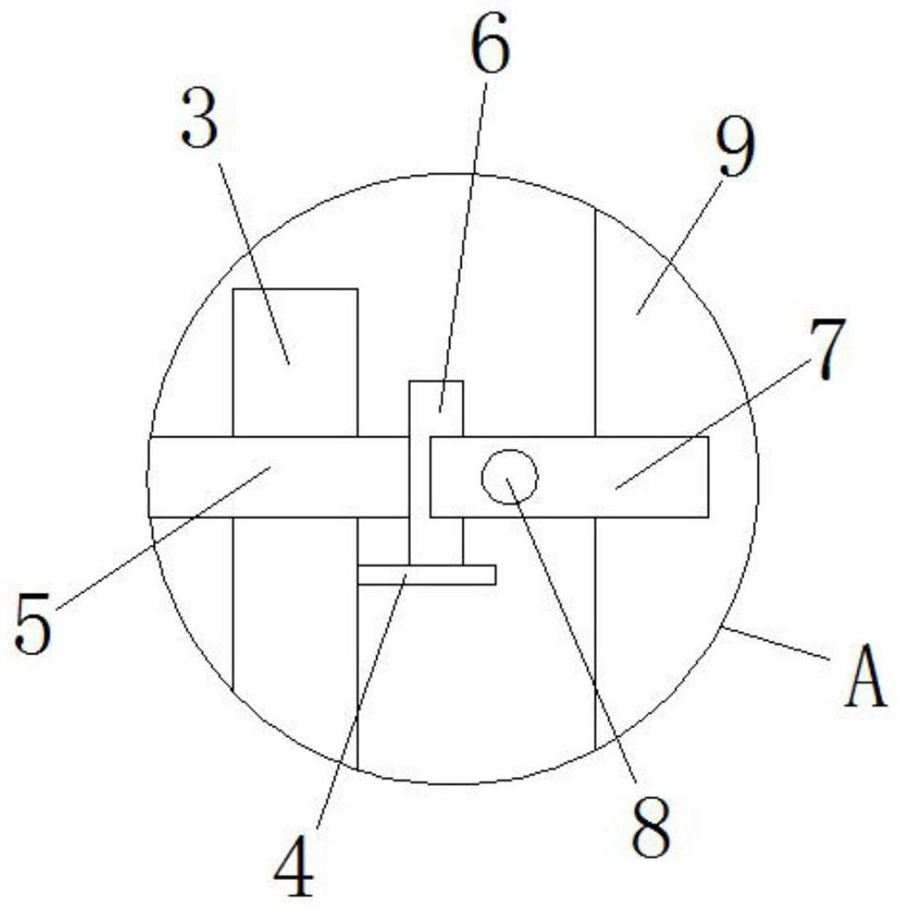
[0024] from Figure 1-5 It can be seen that a steel plate concrete shear wall convenient for positioning in this embodiment includes a base 2 and a shear wall body 9, the bottom of the base 2 is the ground 1, the bottom of the base 2 is attached to the ground 1, and the bottom of the base 2 The upper surface is fixed with a support rod 3, the side of the support rod 3 is fixed with a limit rod 4, the surface of the support rod 3 is equipped with a rotating rod 5, the surface of the rotating rod 5 is fixed with a fixed block 6, and the surface of the fixed block 6 is provided with a stabilizing plate 7. The surface of the stabilizing plate 7 is welded with a spring 21, the surface of the stabilizing plate 7 is installed with a tightening bolt 8, the upper surface of the base 2 is provided with a shear wall body 9, and the upper surface of the shear wall body 9 is equipped with a clamping block 14 , the surface of the block 14 is provided with grooves 16, the two sides of the sh...


PUM


Abstract

The invention discloses a steel plate concrete shear wall which is convenient for positioning, and belongs to the technical field of shear wall bearing capacity experiments. The present invention comprises a base and a shear wall body. A support rod is fixed on the upper surface of the base, a limit rod is fixed on the side of the support rod, a rotating rod is installed on the surface of the supporting rod, and a fixed block is fixed on the surface of the rotating rod. A stabilizing plate is provided on the surface of the block, a shear wall body is provided on the upper surface of the base, and a clamping block is installed on the upper surface of the shear wall body. The invention fixes the body of the shear wall better, so that the phenomenon of falling or swinging back and forth will not occur during the side pull test, so that the experimental data of the steel plate concrete shear wall are more accurate, and the experimenters are more accurate Accurately obtain the data of the bearing capacity of the steel plate concrete shear wall, so that the quality of the bearing capacity of the steel plate concrete shear wall can be improved, and the safety of super high-rise buildings can be improved.

Description

technical field [0001] The invention relates to the technical field of shear wall bearing capacity experiments, and more specifically relates to a steel plate concrete shear wall which is convenient for positioning. Background technique [0002] With the development of society, more and more super high buildings have been erected, and there are many factors to ensure the safety and stability of super high buildings, such as steel plate concrete shear walls, etc. Before designing super high buildings, it is necessary to The designed steel plate concrete shear wall is tested, which requires the use of our steel plate concrete shear wall experiment method. However, most of the test methods for the bearing capacity of steel plate concrete shear walls that are convenient to limit the position have the following problems: 1. The data are not accurate enough. Heavy objects are hung on the side to increase the pressure of the whole method. Since the quality of the heavy objects is ...

Claims


Application Information

Patent Timeline
Patent Type & Authority Patents(China)
IPC IPC(8): E04B2/56
CPCE04B2/56
Inventor 水龙飞王超张宗磊关庆阳
Owner CHINA MCC17 GRP
Learn More