
A paint brush production line with automatic output function

An automatic output and paint brush technology, which is applied in the field of paint brushes, can solve the problems of complex equipment mechanism, high production investment cost, and unsuitability for automatic production, and achieve the effect of high degree of automation, simple structure, and close and complete connection

Active Publication Date: 2021-12-10
徐州斯普瑞喷涂有限公司
View PDF2 Cites 0 Cited by
  • Summary
  • Abstract
  • Description
  • Claims
  • Application Information

AI Technical Summary

Problems solved by technology

[0005] The purpose of the present invention is to address the deficiencies of the prior art. By setting up the handle feeding device, during the feeding process of the handle parts, the horizontal push assembly is used to cooperate with the specific trajectory of the third transmission assembly to complete the clamping of the handle parts. In addition, when the horizontal push component is reset, the paint brush that has been assembled into the finished product is clamped and the material is returned synchronously to realize the automatic output of the finished product, thus solving the complex mechanism of the equipment, the large production investment cost and not suitable for the automatic production of this product technical issues

Method used


Image

  • A paint brush production line with automatic output function
  • A paint brush production line with automatic output function
  • A paint brush production line with automatic output function

Examples


Embodiment 1

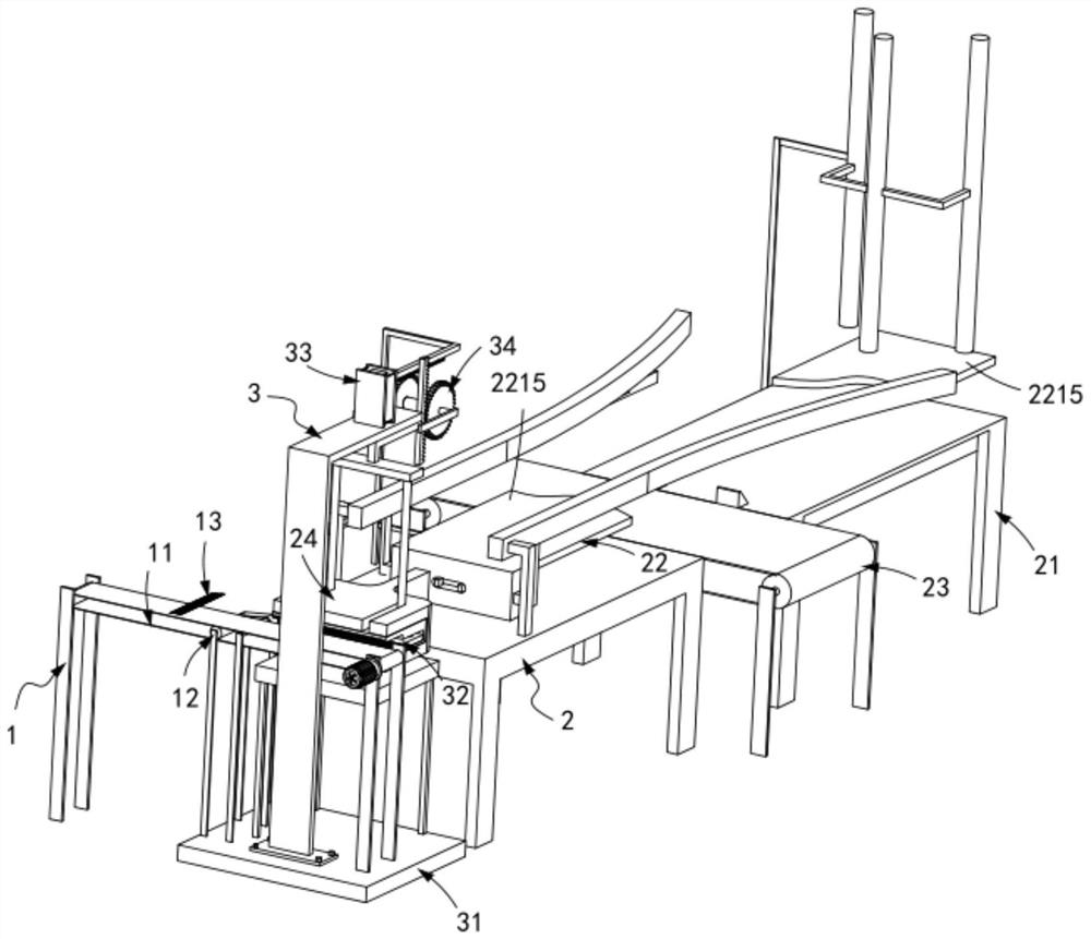
[0075] like figure 1 Shown, a paint brush production line with automatic output, including:

[0076] A bristle feeding device 1, the bristle feeding device 1 includes a first transmission assembly 11 and a second transmission assembly 12 arranged on one side of the first transmission assembly 11, and one end of the bristle component 13 is located on the first transmission assembly 11 and the other end is located on the second transmission assembly 12;

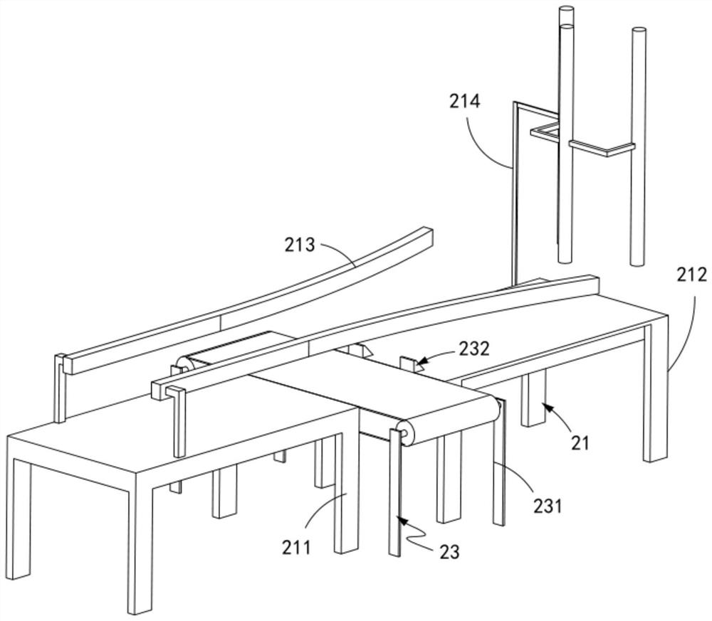
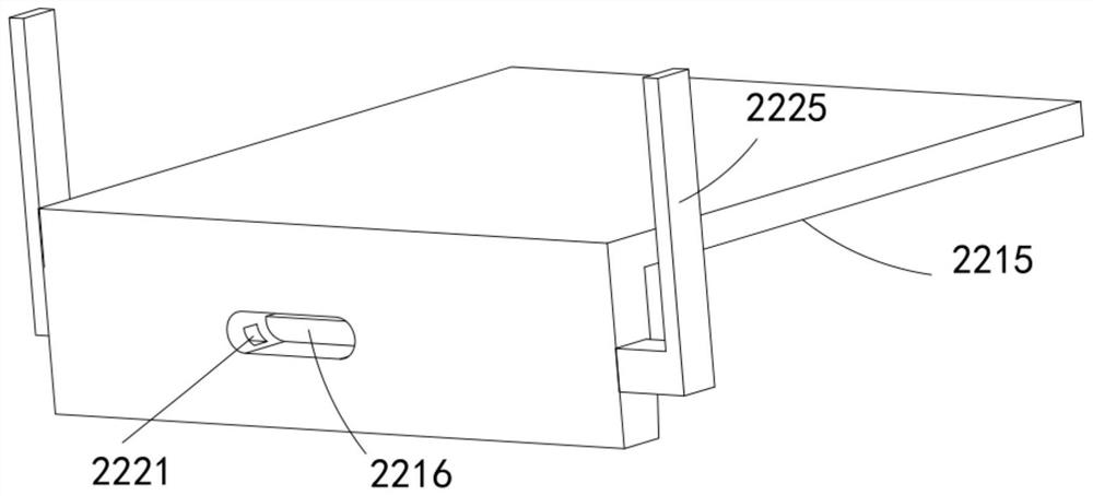
[0077] The handle feeding device 2, the handle feeding device 2 includes a third transmission component 21 arranged perpendicular to the transmission direction of the first transmission component 11, and a push component slidably arranged along the transmission direction of the third transmission component 21 22 and a feeding assembly 23 arranged perpendicular to the third conveying assembly 21 and along the same horizontal plane; and

[0078] An automatic assembly device 3, the automatic assembly device 3 includes a support ...

Embodiment 2

[0131] like Figure 15 As shown, the same or corresponding components as those in the first embodiment are given the corresponding reference numerals as in the first embodiment. For the sake of brevity, only the points of difference from the first embodiment are described below. The difference between the second embodiment and the first embodiment is:

[0132] further, as Figure 15 As shown, the transmission assembly 34 includes:

[0133] a transmission rod a341, the transmission rod a341 is fixedly connected with the driving rod 333 and is arranged perpendicular to it;

[0134] A switching member 342, the switching member 342 includes a rack a3421 fixedly connected to the transmission rod a341 and arranged vertically, a frame e3422 installed on the frame d331, and a rotating shaft c3423 rotatably arranged on the frame e3422 , a gear a3424 meshed with the rack a3421 and fixedly arranged with the rotating shaft c3423, a gear b3425 arranged on the side of the gear a3424 and ...


PUM


Abstract

The invention relates to a paint brush production line with automatic output function, comprising: a bristle feeding device, the bristle feeding device includes a first transmission assembly and a second transmission assembly, one end of the bristle component is located on the first transmission assembly and the other end is on the On the second transmission component: the handle feeding device, the handle feeding device includes a third transmission component, a horizontal push component that is slidably arranged along the transmission direction of the third transmission component, and is vertically arranged with the third transmission component and arranged along the same horizontal plane The feeding assembly; and the automatic assembly device, the automatic assembly device includes a support assembly arranged at the output end of the second transmission assembly and the output end of the third transmission assembly, a clamping part arranged on the support assembly, an extrusion assembly positioned above the clamping part And the transmission assembly fixedly connected with the extrusion assembly and driving the horizontal push assembly to slide back and forth; the invention solves the technical problems that the equipment mechanism is complicated, the production investment cost is large, and it is not suitable for the automatic production of this product.

Description

technical field [0001] The invention relates to the technical field of paint brushes, in particular to a paint brush production line with an automatic output function. Background technique [0002] In the production process of paint brushes in the brush industry, it is an essential process to install the handle of the paint brush head, that is, insert the handle into the brush head filled with glue. At present, the machinery and equipment of my country's brush-making industry is still in the stage of development and improvement. Most of the brush-making machinery is designed and manufactured by each company, with uneven technology, and many processes require pure manual operation. In particular, the handle loading process relies heavily on manual handling, and its production efficiency is not high, the degree of automation is low, and the problems are very prominent. [0003] The patent document with the patent number of CN2016108794304 discloses an automatic handle loading...

Claims


Application Information

Patent Timeline
Patent Type & Authority Patents(China)
IPC IPC(8): A46D3/08A46D3/04
CPCA46D3/085A46D3/082A46D3/08A46D3/04
Inventor 开宗兴
Owner 徐州斯普瑞喷涂有限公司
Learn More