
Static balancing method of a CT rotor

A technology of static balance and rotor, applied in the field of tomographic scanning medical equipment, can solve the problems of poor calculation accuracy, cumbersome operation, driving speed, uniformity difference, etc., and achieve the effect of eliminating the interference of non-unbalanced factors, simple operation and high precision

Inactive Publication Date: 2020-02-07
FMI MEDICAL SYST CO LTD
View PDF4 Cites 6 Cited by
  • Summary
  • Abstract
  • Description
  • Claims
  • Application Information

AI Technical Summary

Problems solved by technology

But there are the following problems: When measured by the push-pull force meter, due to the difference in static friction and dynamic friction, the difference in pushing speed, the difference in uniformity, and the difference in individual angle defects, the thrust values ​​of different people and different orders are quite different, which is not accurate enough; additional Thrust gauges need to be operated manually, which is cumbersome and inefficient
The thrust difference at each angle of a circle cannot be identified, the calculation accuracy is poor, and the thrust change caused by non-unbalance factors cannot be ruled out

Method used


Image

  • Static balancing method of a CT rotor
  • Static balancing method of a CT rotor

Examples


Embodiment Construction

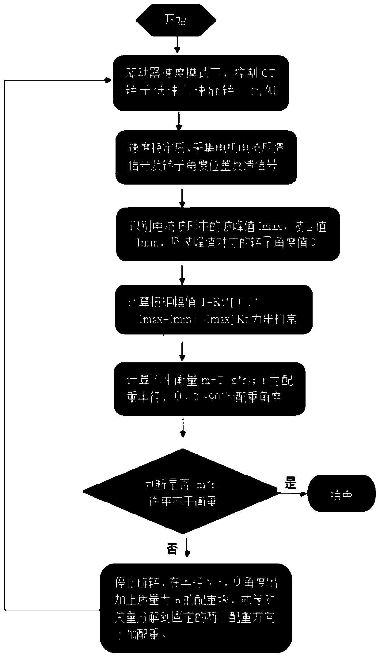
[0015] refer to figure 1 A specific implementation of a static balancing method for a CT rotor of the present invention will be further described.

[0016] A static balancing method for a CT rotor, comprising the steps of:

[0017] (1) In the drive speed mode, control the CT rotor to rotate at a low speed of 4-6rpm;

[0018] (2) After the speed is stable, collect the motor current feedback signal and the rotor angle position feedback signal;

[0019] (3) Identify the peak value Imax, the valley value Imin, and the rotor angle value α corresponding to the peak value in the current waveform;

[0020] (4) Calculate the torque amplitude T=Kt*[(0.5*(Imax+Imin)-Imax], Kt is the motor constant;

[0021] (5) Calculate the unbalance m=T / (g*r); r is the radius of the counterweight, θ=α+90° is the angle of the counterweight;

[0022] (6) Termination judgment: if the unbalanced amount m*r is less than the allowable unbalanced amount, end; otherwise stop the rotation, add a counterweig...


PUM


Abstract

The invention discloses a static balancing method of a CT rotor. The method comprises the following steps of (1) controlling the CT rotor to rotate at the constant low speed of 4-6rpm in a driver speed mode, (2) collecting a motor current feedback signal and a rotor angle position feedback signal after the speed is stabilized, (3) identifying a wave peak value Imax, a wave trough value Imin, and arotor angle value alpha corresponding to the wave peak value in a current waveform; (4) calculating torque amplitude T=Kt*[0.5*(Imax+Imin)-Imax], wherein Kt is a motor constant; and (5) calculating the amount of unbalance m=T / (g*r), wherein r is balance weight semi-diameter, and the theta is equal to alpha+90 degrees as the balance weight angle. Through the static balancing method of the CT rotordisclosed by the invention, the amount of the unbalance and the position can be automatically identified, an additional extra instrument is unnecessary, the operation is simple, and the efficiency ishigh; and the method is free from the influence of a human factor, the amount of unbalance factor interface can be eliminated, and the precision is high.

Description

technical field [0001] The invention relates to the technical field of tomographic scanning medical devices, and more particularly relates to a static balancing method for a CT rotor. Background technique [0002] In the prior art, the static unbalance of the CT rotor is measured by a push-pull dynamometer to measure the difference in thrust at different angles, and the size and position of the unbalance are identified for trimming. But there are the following problems: When measured by the push-pull force meter, due to the difference in static friction and dynamic friction, the difference in pushing speed, the difference in uniformity, and the difference in individual angle defects, the thrust values ​​of different people and different orders are quite different, which is not accurate enough; additional The thrust gauge has to be manually operated, which is cumbersome and inefficient. The thrust difference at each angle of a circle cannot be identified, and the calculation...

Claims


Application Information

Patent Timeline
IPC IPC(8): G01M1/22
CPCG01M1/22
Inventor 潘险峰王瑶法马兴江
Owner FMI MEDICAL SYST CO LTD
Learn More