
To-ground aiming mechanism used for space camera

A space camera and component technology, applied in the field of aerospace remote sensing, can solve the problems of high power consumption and poor maneuverability, and achieve the effects of low power consumption, good maneuverability and fast adjustment speed

Active Publication Date: 2020-02-07
CHANGGUANG SATELLITE TECH CO LTD
View PDF6 Cites 0 Cited by
  • Summary
  • Abstract
  • Description
  • Claims
  • Application Information

AI Technical Summary

Problems solved by technology

[0004] The present invention aims to solve the problem of poor maneuverability and high power consumption when adjusting the overall attitude of the satellite in the existing satellite sideways imaging process, and further provides a ground-pointing mechanism for space cameras

Method used


Image

  • To-ground aiming mechanism used for space camera
  • To-ground aiming mechanism used for space camera
  • To-ground aiming mechanism used for space camera

Examples


specific Embodiment approach 1

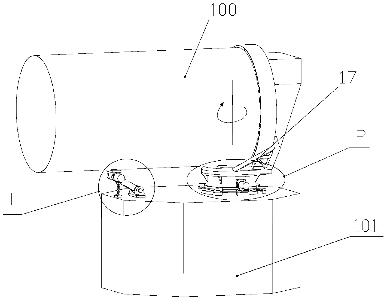
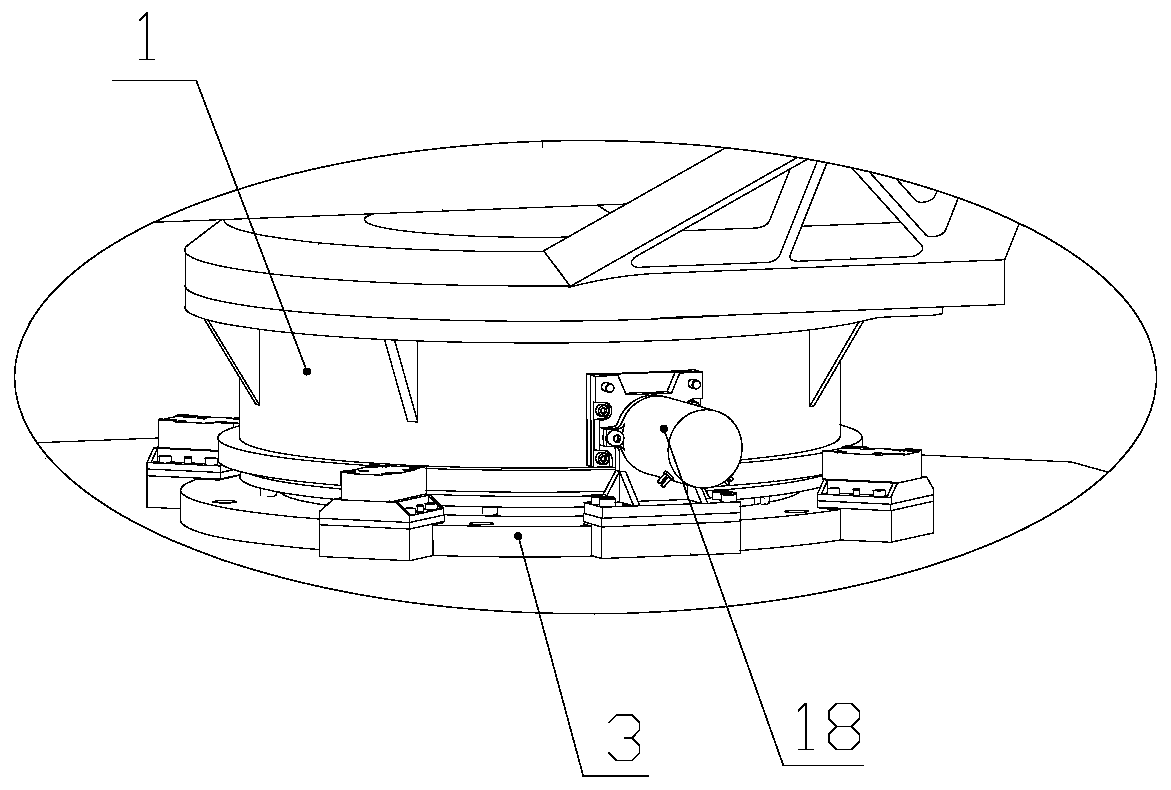
[0027] Specific implementation mode one: combine Figure 1-5 Describe the present embodiment, a space camera ground aiming mechanism, which includes a space camera 100, a satellite platform 101 and a mechanism body arranged between the space camera and the satellite platform, the mechanism body includes a shaft assembly, a feedback assembly and A drive assembly that controls the movement of the shafting assembly, wherein the shafting assembly includes a turntable 1, a fixed inner shaft 2 and a base 3, the fixed inner shaft 2 has a ring structure and one end is fixed on the base 3, so The turntable 1 is rotatably set on the fixed inner shaft 2, the top of the turntable 1 is fixedly connected to the space camera 100 through the adapter 17, and the base 3 is fixedly connected to the satellite platform 101.

[0028] The feedback assembly includes a moving inner shaft 5, a photoelectric encoder 6 and a fixed flange 7, the moving inner shaft 5 is installed in the fixed inner shaft 2...


PUM


Abstract

The invention discloses a to-ground aiming mechanism used for a space camera and belongs to the technical field of space remote sensing. By means of the mechanism, the problems that overall satelliteattitude adjustment is poor in maneuverability and large in power consumption during existing satellite side swinging imaging are solved. A shafting assembly comprises a turnplate, a fixed inner shaftand a base. The fixed inner shaft is of an annular structure, and one end of the fixed inner shaft is fixedly mounted on the base. The turnplate is rotationally arranged on the fixed inner shaft in asleeving mode. The base is fixedly connected with a satellite platform. A feedback assembly comprises a movable inner shaft, an optical-electricity encoder and a fixed flange. The movable inner shaftis mounted in the fixed inner shaft in a penetrating mode, and the upper portion of the movable inner shaft is coaxially and fixedly connected with the turnplate. An inner ring of the optical-electrictiy encoder sleeves the movable inner shaft. An outer ring of the optical-electricity encoder is fixedly connected with the fixed flange through the fixed inner shaft. A driving assembly comprises aceramic ring and a plurality of ultrasonic motors. The ceramic ring is coaxially arranged on the lower portion of the turnplate in a sleeving mode. The multiple ultrasonic motors are fixedly mounted on the base and distributed uniformly in the circumferential direction of the turnplate. Ceramic legs of each ultrasonic motor make contact with the ceramic ring in a matched mode.

Description

technical field [0001] The invention relates to a ground aiming mechanism for a space camera, which belongs to the technical field of aerospace remote sensing. Background technique [0002] The existing large-angle satellite side-sway imaging technology uses components such as reaction flywheels and control moment gyroscopes to realize the large-angle side-sway or pitch-yaw maneuver of the entire satellite, and to image the adjacent areas of the sub-satellite point. [0003] The disadvantages of this side-swing imaging are: a) Poor maneuverability and high power consumption. It is difficult to achieve a fast speed for large-angle maneuvering of the entire satellite by relying on flywheels, control moment gyroscopes and other components, especially when the overall mass of the satellite is large, and it is difficult to achieve Fast maneuvering; b) low reliability and high failure rate of the control moment gyro; c) high power consumption, and large-angle maneuvering of the en...

Claims


Application Information

Patent Timeline
Patent Type & Authority Applications(China)
IPC IPC(8): B64G1/10B64G1/66G03B17/56
CPCB64G1/10B64G1/66G03B17/561B64G1/223
Inventor 张雷霍占伟丛杉珊袁健
Owner CHANGGUANG SATELLITE TECH CO LTD
Learn More