
Shearing device

A shearing device and blade technology, which is applied in the direction of shearing devices, shearing machine accessories, shearing machine equipment, etc., can solve problems such as high work intensity, low work efficiency, and potential safety hazards, so as to improve work efficiency and reduce work costs. Strength, the effect of realizing high-altitude operations

Pending Publication Date: 2020-02-07
STATE GRID PUTIAN ELECTRIC POWER SUPPLY +1
View PDF0 Cites 0 Cited by
  • Summary
  • Abstract
  • Description
  • Claims
  • Application Information

AI Technical Summary

Problems solved by technology

[0002] In the power grid, the conductive strip is generally used on the connection of two conductive arms. Some conductive sheets in the conductive strip will be oxidized, rusted and broken after long-term use, and manual maintenance is required. Due to the limited conditions of the power supply company, maintenance needs It meets the requirements of live work, and belongs to high-altitude work, which has high potential safety hazards. The original maintenance relies on manual insulating clamps to directly bend and break the conductive sheet repeatedly, and then remove it. The work intensity is high and the work efficiency is low. There are security risks

Method used


Image

  • Shearing device
  • Shearing device
  • Shearing device

Examples


Embodiment Construction

[0019] The present invention will be further described below in conjunction with the accompanying drawings and specific embodiments.

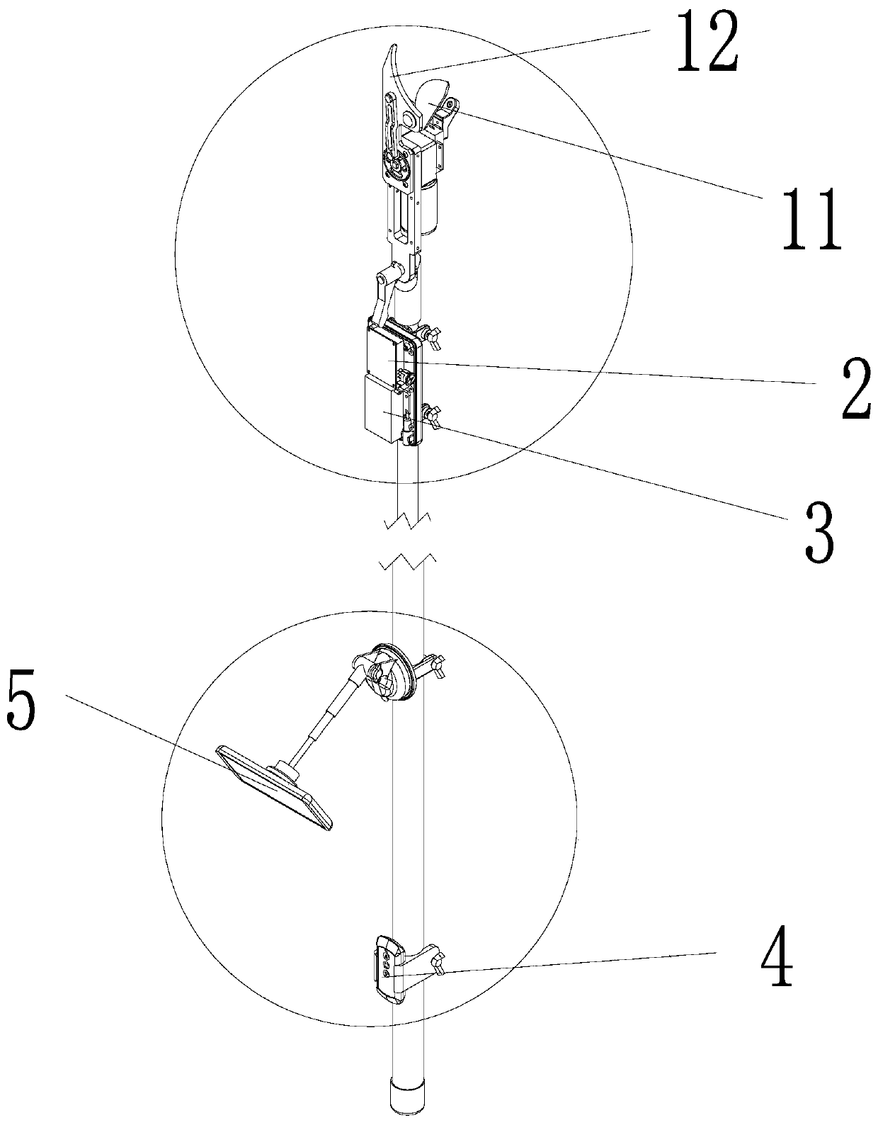
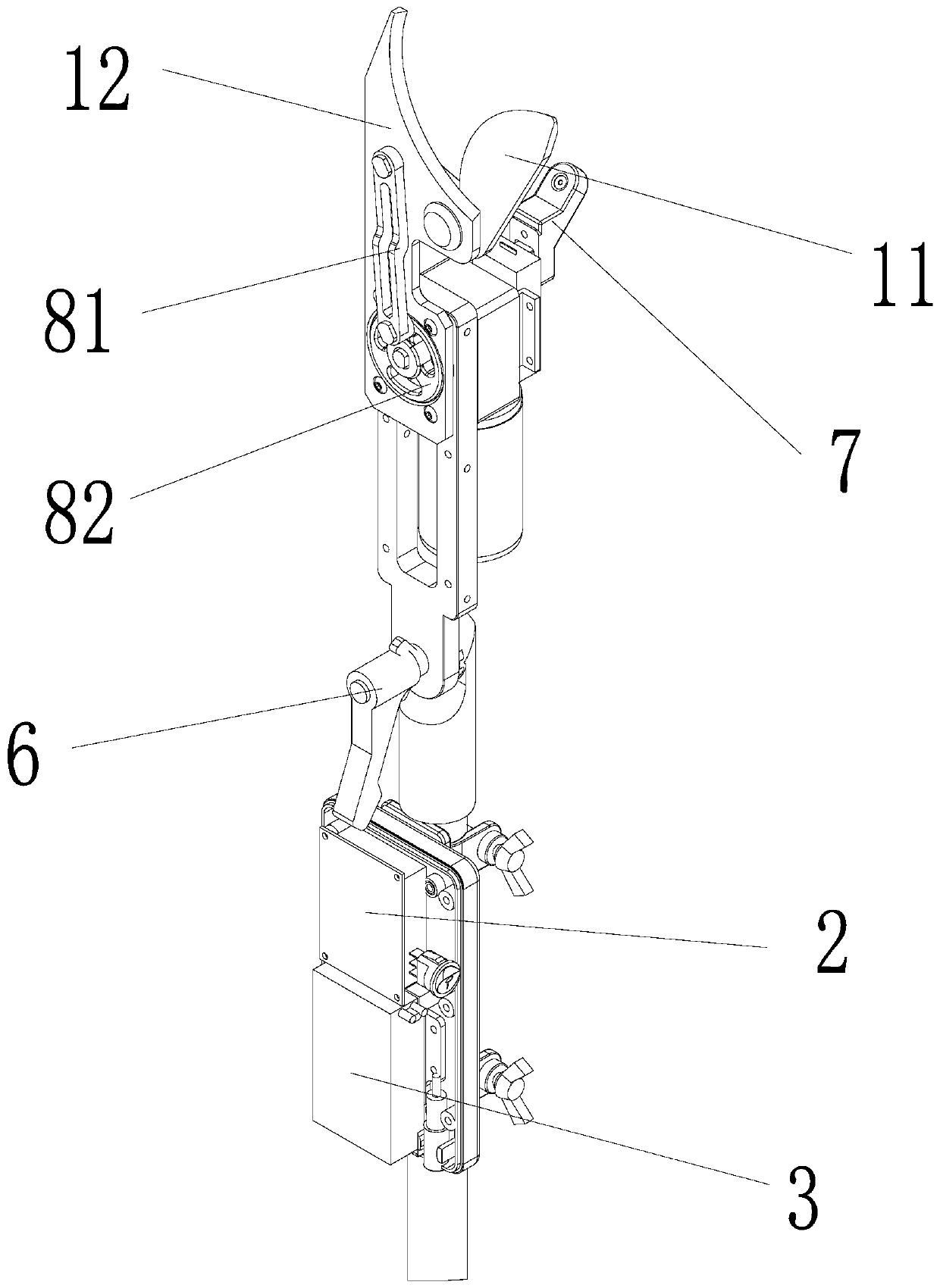
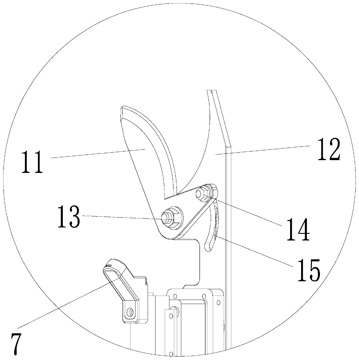
[0020] A shearing device, refer to Figures 1 to 4 , including a cutting module and a control module; the cutting module includes a first blade 11 and a second blade 12; the first blade 11 is rotationally connected to the second blade 12;

[0021] It also includes a linkage mechanism that drives the first blade 11 to rotate; the control module includes a power output mechanism, and the power output mechanism is connected to the linkage mechanism; the control module includes a control board 2 and a control switch, and the control board 2. Connect the power output mechanism; the power output mechanism, the control panel 2 and the control switch are all connected to a power supply 3, the control switch is turned on, and the power output mechanism, the control panel 2 and the control switch are all powered on; The control board 2 sends an activati...


PUM


Abstract

The invention provides a shearing device. The shearing device comprises a shearing module and a control module. The shearing module comprises a first blade and a second blade rotatably connected withthe first blade. The shearing module further comprises a linking mechanism used for driving the first blade to rotate. The control module comprises a power output mechanism connected with the linkingmechanism and further comprises a control panel and a control switch, wherein the control panel is connected with the power output mechanism. The power output module, the control panel and the controlswitch are all connected with a power supply. When the control switched is turned on, the power output mechanism, the control panel and the control switch are all powered on. The control panel sendsa starting signal to the power output mechanism. The power output mechanism drives the linking mechanism to move to enable the first blade to rotate and to achieve clamping and shearing together withthe second blade. By the adoption of the technical scheme, the work time of workers can be effectively shortened.

Description

technical field [0001] The invention relates to the field of live working, in particular to a shearing device. Background technique [0002] In the power grid, the conductive strip is generally used on the connection of two conductive arms. Some conductive sheets in the conductive strip will be oxidized, rusted and broken after long-term use, and manual maintenance is required. Due to the limited conditions of the power supply company, maintenance needs It meets the requirements of live work, and belongs to high-altitude work, which has high potential safety hazards. The original maintenance relies on manual insulating clamps to directly bend and break the conductive sheet repeatedly, and then remove it. The work intensity is high and the work efficiency is low. There are security risks. Contents of the invention [0003] The purpose of the present invention is to provide a shearing device, which can effectively reduce the working time of operators. [0004] In order to ...

Claims


Application Information

Patent Timeline
Patent Type & Authority Applications(China)
IPC IPC(8): B23D31/00B23D33/00
CPCB23D31/00B23D33/00
Inventor 柯拥勤李振华林益鹤林明星李敏王科新郭琪敏
Owner STATE GRID PUTIAN ELECTRIC POWER SUPPLY
Learn More