Display panel

A display panel and display area technology, which is applied in the direction of semiconductor devices, electrical components, circuits, etc., can solve the problems of organic packaging layer overflow, unfavorable setting method and narrow frame of the display panel, etc., so as to reduce the probability of overflow and realize narrow The effect of borders

Active Publication Date: 2020-02-04
KUNSHAN GO VISIONOX OPTO ELECTRONICS CO LTD
View PDF14 Cites 5 Cited by
  • Summary
  • Abstract
  • Description
  • Claims
  • Application Information

AI Technical Summary

Problems solved by technology

[0003] However, due to the limitation of process precision, in the process of forming the organic encapsulation layer, the organic encapsulation layer still overflows to the outside of the dam, and the arrangement of the above-mentioned multiple dams is not conducive to the realization of the narrow frame of the display panel

Method used


Image

  • Display panel
  • Display panel
  • Display panel

Examples


Embodiment Construction

[0022] The following will clearly and completely describe the technical solutions in the embodiments of the present application with reference to the drawings in the embodiments of the present application. Obviously, the described embodiments are only some of the embodiments of the present application, not all of them. Based on the embodiments in this application, all other embodiments obtained by persons of ordinary skill in the art without making creative efforts belong to the scope of protection of this application.

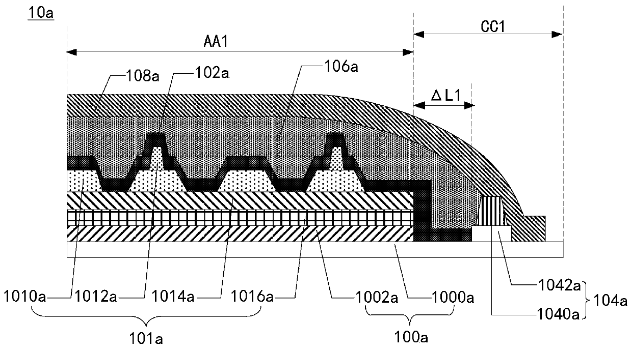
[0023] see figure 1 , figure 1 It is a schematic structural diagram of an embodiment of the display panel of the present application. The display panel 10 can be an OLED display panel, a Micro-OLED display panel, etc., and includes: an array film layer 100 , a first inorganic encapsulation layer 102 , a hydrophobic barrier structure 104 , an organic encapsulation layer 106 , and a second inorganic encapsulation layer 108 .

[0024] Specifically, the array fi...


PUM


Abstract

The invention provides a display panel. The display panel comprises an array film layer, a first inorganic packaging layer, a hydrophobic barrier structure, an organic packaging layer and a second inorganic packaging layer, wherein the array film layer is provided with a display area and a non-display area located at the periphery of the display area; the first inorganic packaging layer covers thedisplay area and extends to the non-display area; the hydrophobic barrier structure is arranged at the periphery of the first inorganic packaging layer so as to enclose the first inorganic packaginglayer therein; the organic packaging layer covers the first inorganic packaging layer, extends to the non-display area and is stopped at the hydrophobic barrier structure; and the second inorganic packaging layer covers the organic packaging layer, extends to the non-display area and covers the hydrophobic barrier structure. The probability of overflow of the organic packaging layer during the forming process can be reduced through the above mentioned approach.

Description

technical field [0001] The present application relates to the field of display technology, in particular to a display panel. Background technique [0002] At present, the display panel generally adopts the form of thin film encapsulation to improve its flexibility. The specific structure of the thin film encapsulation includes: a first inorganic encapsulation layer, an organic encapsulation layer, and a second inorganic encapsulation layer arranged in layers. Wherein, a plurality of dams are generally arranged at the boundary of the organic encapsulation layer, and the plurality of dams are used to limit the position of the organic encapsulation layer. [0003] However, due to the limitation of process precision, the organic encapsulation layer still overflows to the outside of the dam during the process of forming the organic encapsulation layer, and the arrangement of the above-mentioned multiple dams is not conducive to the realization of a narrow frame of the display pa...

Claims


Application Information

Patent Timeline
IPC IPC(8): H01L51/52H01L27/32
CPCH10K59/122H10K59/12H10K50/844
Inventor 杜佳梅刘亚伟宋玉华王淑鹏金世遇
Owner KUNSHAN GO VISIONOX OPTO ELECTRONICS CO LTD
Why Eureka
Try Eureka