A motor rotor cooling system for an electric drive assembly

A motor rotor and cooling system technology, which is applied to the layout of the cooling combination of power plants, motors, electric vehicles, etc., can solve the problems of unfavorable integrated design of electric drive assembly, small heat exchange area of ​​coolant, and insufficient cooling effect , to achieve the effect of reducing the structural mass, ensuring the cooling effect, and reducing the mass

Active Publication Date: 2022-07-12
NINGBO PHASE MOTION CONTROL
View PDF0 Cites 0 Cited by
  • Summary
  • Abstract
  • Description
  • Claims
  • Application Information

AI Technical Summary

Problems solved by technology

This solution adopts the form of an external coolant circuit, which needs to be installed and fixed, which takes up a large space, which is not conducive to the integrated design of the electric drive assembly; The liquid heat exchange area is small and the cooling effect is insufficient

Method used


Image

  • A motor rotor cooling system for an electric drive assembly
  • A motor rotor cooling system for an electric drive assembly
  • A motor rotor cooling system for an electric drive assembly

Examples


Embodiment Construction

[0023] According to the following Figure 2 to Figure 5 The specific embodiments of the present invention are further described:

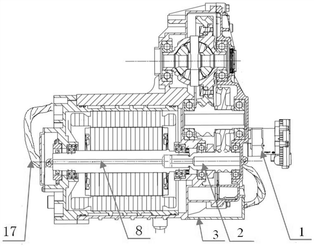
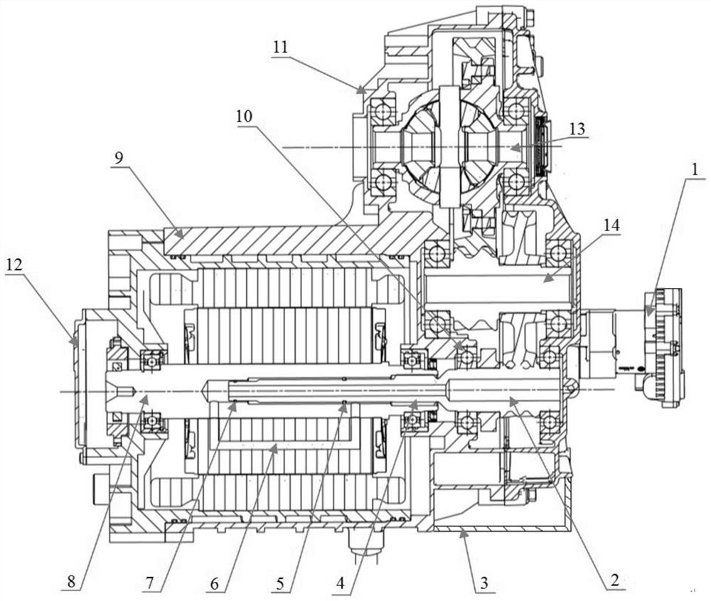
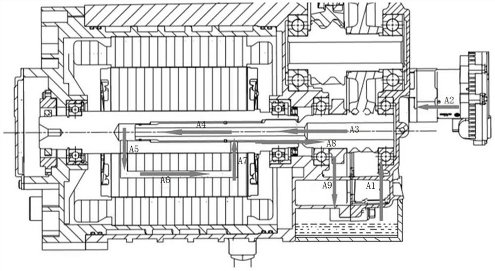
[0024] This embodiment provides a motor rotor cooling system for an electric drive assembly, such as figure 2 As shown, including pump 1, oil pan 3, motor rotor, reducer hollow input shaft 2, motor housing 9, bearing 10 at the front end of reducer hollow input shaft 2, bearing 10 at the rear end of reducer hollow input shaft 2, reducer Housing 11 , motor rear housing 12 , reducer differential assembly 13 , reducer intermediate shaft assembly 14 .

[0025] like figure 2 As shown, the motor rotor of this embodiment includes a motor rotor lamination core and a motor hollow shaft 8 fixed inside the motor rotor lamination core. The oil suction port of the pump 1 is immersed in the oil pan 3, and the pump 1 The oil outlet is sealed with one end of the hollow input shaft 2 of the reducer, the other end of the hollow input shaft 2 of the reducer is in...


PUM


Abstract

The invention discloses a motor rotor cooling system for an electric drive assembly, comprising a pump, an oil pan, a motor rotor and a hollow input shaft of a reducer. Submerged in the oil pan, the oil outlet of the pump is sealed with the hollow input shaft of the reducer, the hollow input shaft of the reducer is inserted into the inner hole of the hollow shaft of the motor, and the hollow input shaft of the reducer and the hollow shaft of the motor are connected by a spline structure. There are oil passages inside the laminated iron core of the rotor of the motor. The hollow shaft of the motor is respectively provided with a front oil outlet and a rear oil return port which communicate with the oil passages. The front oil outlet is connected to one end of the hollow input shaft of the reducer, and the rear row The oil return port is communicated with the oil pan through the gap between the hollow rotating shaft of the motor and the hollow input shaft of the reducer, and the spline structure in turn; the invention increases the heat exchange area between the cooling liquid and the motor rotor through the built-in cooling liquid circuit, and greatly improves the cooling effect. Efficiency, efficient coolant circulation.

Description

technical field [0001] The invention relates to a cooling system for an electric drive assembly of a new energy vehicle, in particular to a motor rotor cooling system for an electric drive assembly. Background technique [0002] Under the development theme of energy conservation and environmental protection, the state has issued many support policies for new energy vehicles, and new energy vehicle technologies continue to be updated iteratively. Power is delivered more efficiently, and the cooling performance of the powertrain is more challenging. At present, the motor cooling system of the electric drive assembly is mainly aimed at the motor stator, and the thermal management of the motor rotor will become an important topic of motor cooling. The motor will generate a lot of heat under extreme conditions such as maintaining the car ramp, starting and accelerating rapidly. If the temperature control is unreasonable, it will directly affect the output power, insulation perfo...

Claims


Application Information

Patent Timeline
Patent Type & Authority Patents(China)
IPC IPC(8): B60K11/02
CPCB60K11/02Y02T10/64
Inventor 杨先时牛波牛正蕊应迎策
Owner NINGBO PHASE MOTION CONTROL
Why Eureka
Try Eureka