Strain wave gear mechanism with inner seal

A technology of gear mechanism and inner seal, which is applied to the sealing of engines, belts/chains/gears, manipulators, etc., and can solve problems such as lubricant leakage and premature dry operation of gear mechanisms

Active Publication Date: 2020-01-24
HARMONIC DRIVE INC
View PDF6 Cites 1 Cited by
  • Summary
  • Abstract
  • Description
  • Claims
  • Application Information

AI Technical Summary

Problems solved by technology

However, such sealing rings are often not able to withstand the high load of gear mechanism lubricant, so that undesired lubricant leakage occurs
Such a lubricant leakage can lead to the fact that within the gear mechanism on the side facing away from the toothing, there is almost no return of the consumed lubricant, which increases the additional lubricant quantity required due to the travel movement and the gear mechanism can dry out prematurely. run

Method used


Image

  • Strain wave gear mechanism with inner seal
  • Strain wave gear mechanism with inner seal
  • Strain wave gear mechanism with inner seal

Examples


Embodiment Construction

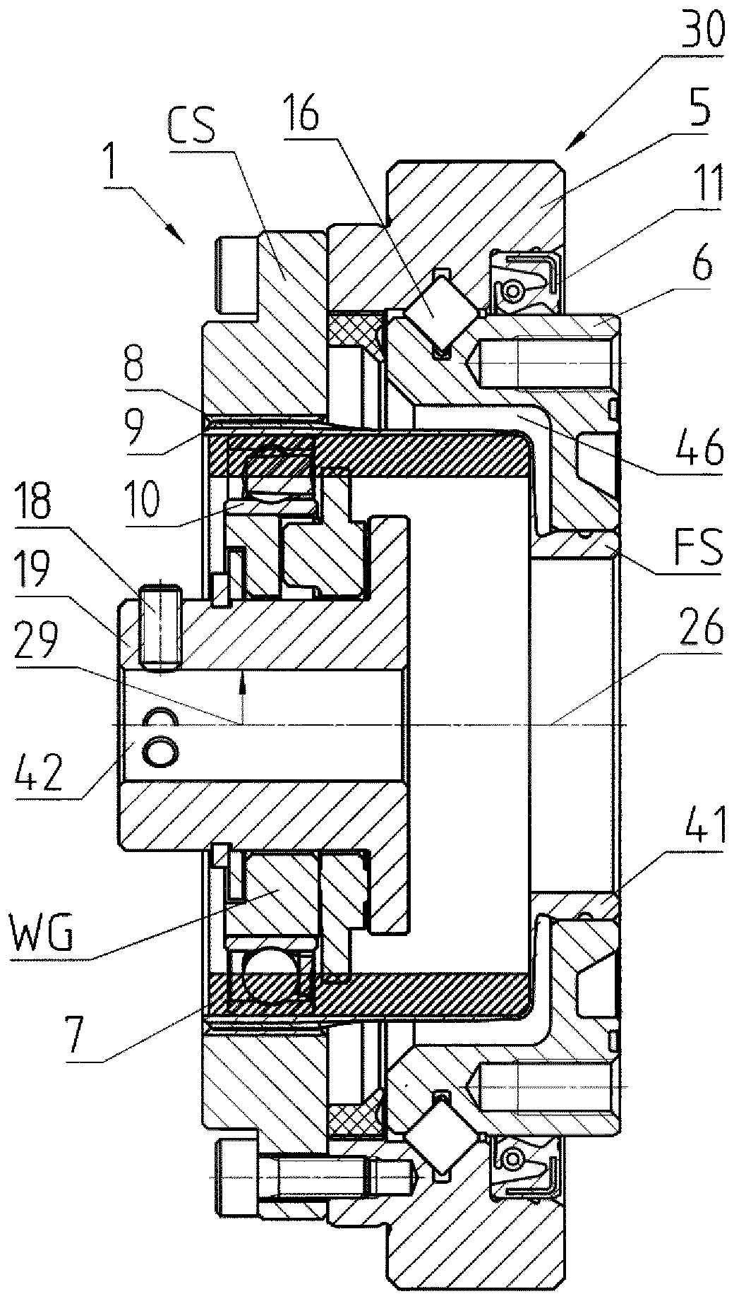
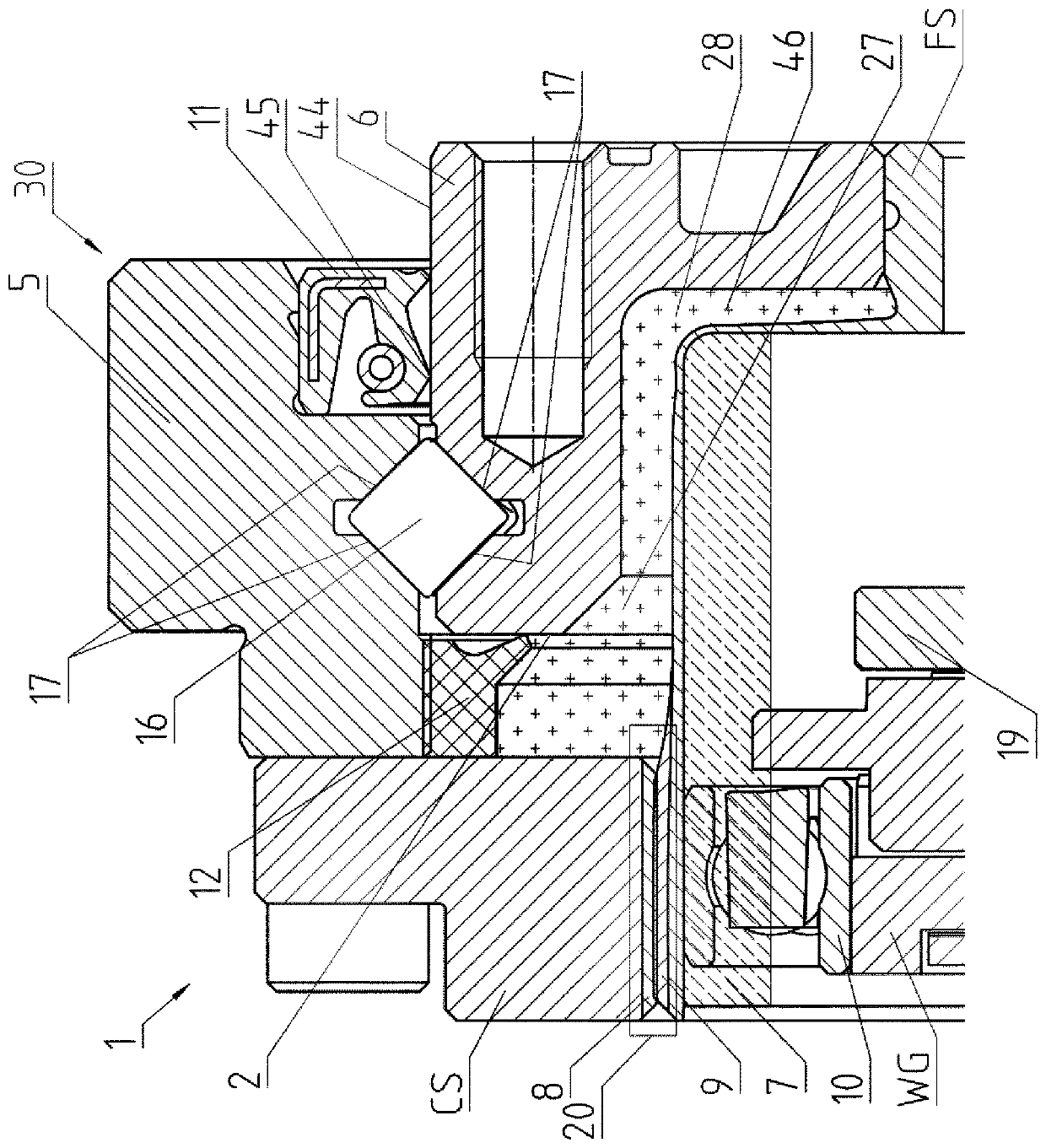
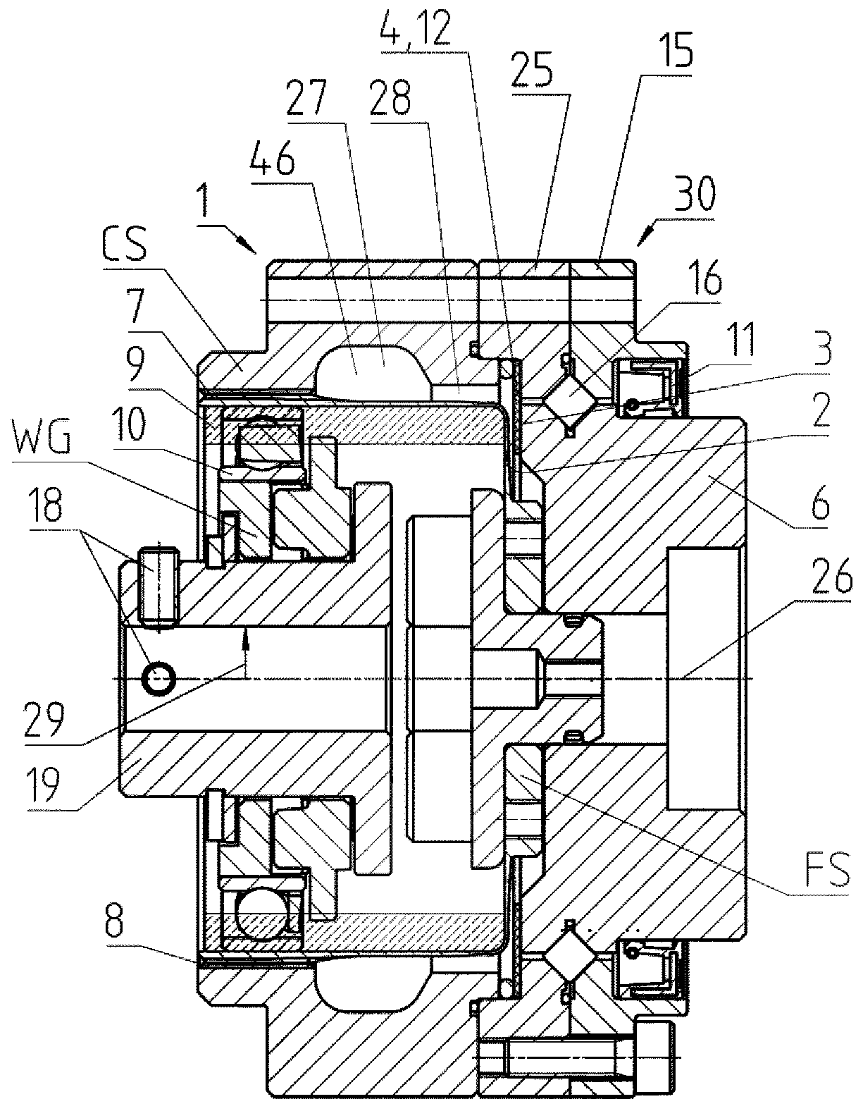
[0045] figure 1 A first exemplary embodiment of a stress wave gear mechanism 1 is shown, which has a gear mechanism component CS configured as an internal gear, which in the region of its internal toothing 8 overlaps the external toothing 9 of the transmission component FS and Engage regionally. The transmission component FS is connected in a rotationally fixed manner to the inner bearing ring 6 of the swivel bearing 30 , which mounts the transmission component FS and the gear mechanism component CS rotatably relative to each other. The outer bearing ring 5 of the swivel bearing 30 is connected in a rotationally fixed manner to the gear train component CS. Like the transmission component FS, a plug 41 is provided in a rotationally fixed manner, which enables the positioning of the stress wave gear 1 relative to the stress wave gear 1 . figure 1 The output side on the right is blocked.

[0046] Along the transmission axis 26 , about which the components of the stress wave ge...


PUM


Abstract

The invention relates to a strain wave gear mechanism (1) with a gear mechanism component (CS) and an elastically deformable transmission component (FS) which is at least partially in alignment therewith in the radial direction (29) and can be deformed elliptically by way of a drive component (WG) which interacts therewith, in such a way that internal or external toothing systems (8, 9) which areprovided on the gear mechanism component (CS) and the transmission component (FS) can be brought into engagement in opposite regions of an elliptical axis, in order to rotate the transmission component (FS) and the gear mechanism component (CS) relative to one another, wherein the transmission component (FS) and the gear mechanism component (CS) are mounted such that they can be rotated relative to one another by means of a pivot bearing (30) which has a bearing intermediate space (16). In order that the risk of a lubricant leak and/or premature dry running of the gear mechanism can be reducedreliably, there is a strain wave gear mechanism, in the case of which an interior space (28) of the strain wave gear mechanism (1), which interior space (28) is enclosed at least partially by the transmission component (FS) and the internal or external toothing system (8, 9) and adjoins the pivot bearing (30), is sealed by means of an inner seal (12) with respect to the bearing intermediate space(16) of the pivot bearing.

Description

technical field [0001] The invention relates to a stress wave gear mechanism according to the preamble of claim 1 . Background technique [0002] Such gear mechanisms are used in various ways in various fields of technology, and they are especially frequently used in robotics and prosthetics. Reference is made here exemplarily to the applicant's Harmonie Transmissions, which belong to the group of stress wave gear mechanisms and whose principle of action is described, for example, at http: / / harmonicdrive.de / technoloqie / harmonic-drive-wellqetriebe / . Harmonie is a registered trademark of Hamenacor Drives AG, Limburg an der Lahn. [0003] In the traditional type of construction of a stress wave gear mechanism, where a drive member called an elliptical "wave generator" deforms a transmission member called an external flexspline via a rolling bearing, the transfer member is at the length of the ellipse In the opposite area of ​​the axis, it meshes with an internally meshing...

Claims


Application Information

Patent Timeline
Patent Type & Authority Applications(China)
IPC IPC(8): F16H49/00
CPCF16H49/001F16H57/0469F16J15/022F16J15/32B25J9/1025F16H57/025F16H57/029F16H57/0454F16H2049/003
Inventor M·门德尔M·沙费尔D·格贝尔A·阿尔滕J·P·克嫩
Owner HARMONIC DRIVE INC
Why Eureka
Try Eureka