Transformer convenient to lift

A technology of transformers and lifting rings, applied in transformer handling devices, transformer/inductor components, transformer/reactor installation/support/suspension, etc., can solve the problems of heavy handling and inconvenience of transformers, and achieve convenient handling and increase freedom resistance, reducing the effect of cracking damage

Inactive Publication Date: 2020-01-17
海安隆久机电科技有限公司
View PDF5 Cites 0 Cited by
  • Summary
  • Abstract
  • Description
  • Claims
  • Application Information

AI Technical Summary

Problems solved by technology

[0002] Transformers are heavy and inconvenient to carry, so it is necessary to provide a technical solution to solve such technical problems

Method used


Image

  • Transformer convenient to lift

Examples


Embodiment Construction

[0007] The present invention will be further described below in conjunction with the accompanying drawings and specific embodiments.

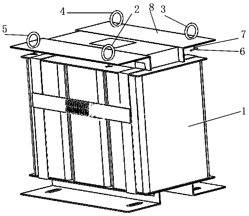
[0008] figure 1 Middle: Transformer body 1, first suspension ring 2, second suspension ring 3, third suspension ring 4, fourth suspension ring 5, bayonet pin 6, connecting rod 7, upper top plate 8.

[0009] A transformer that is easy to lift. The transformer that is easy to lift includes a transformer body 1, a first lifting ring 2, a second lifting ring 3, a third lifting ring 4, and a fourth lifting ring 5. The first lifting ring 2, the second lifting ring 3, The third lifting ring 4, the fourth lifting ring 5 are welded to one end of the connecting rod 7, and the other end of the connecting rod 7 is welded with a horizontal bayonet pin 6. The welding process: first the first lifting ring 2, the second lifting ring 3 , the third suspension ring 4, the fourth suspension ring 5 are welded to one end of the connecting rod 7, then the connecting...


PUM


Abstract

The invention provides a transformer convenient to lift. The transformer convenient to lift comprises a transformer body, a first lifting ring, a second lifting ring, a third lifting ring and a fourthlifting ring, bayonet locks are welded to the first lifting ring, the second lifting ring, the third lifting ring and the fourth lifting ring through connecting rods, and the connecting rods penetrate through an upper top plate of the transformer body through holes. The transformer has the beneficial effects that the transformer can be carried by multiple persons and can be carried more conveniently.

Description

technical field [0001] The invention relates to a mechanical device, in particular to an easy-to-lift transformer. Background technique [0002] The transformer is relatively bulky and thus very inconvenient to carry, so it is necessary to provide a technical solution to solve such technical problems. Contents of the invention [0003] The invention provides an easy-to-lift transformer. The purpose of designing and developing the device is that the device is convenient to be carried by multiple people, so that the transfer of the transformer is more convenient. [0004] The present invention provides the following technical solutions: a transformer that is easy to lift, the transformer that is easy to lift includes a transformer body 1, a first suspension ring 2, a second suspension ring 3, a third suspension ring 4, and a fourth suspension ring 5. One ring 2 , the second ring 3 , the third ring 4 , and the fourth ring 5 are welded with bayonet pins 6 through connecting r...

Claims


Application Information

Patent Timeline
IPC IPC(8): H01F27/00H01F27/06
CPCH01F27/002H01F27/06
Inventor 朱海军严晓东吕友劲张军吴宗昆彭姝涵吴同罗兰
Owner 海安隆久机电科技有限公司
Why Eureka
Try Eureka